Home -> Laser Cutting services
Precision Laser Cutting Services for OEM Manufacturing
Looking for higher precision and lower-cost laser cutting solutions? Leveraging a megawatt-level laser equipment cluster and the high-precision TRUMPF 5030 cutting system, SR MFG delivers ±0.03 mm precision machining and provides customized metal laser cutting services that can improve material utilization by up to 18%.
Why choose SR MFG for Custom Laser Cutting?
High-precision, stable and mass laser cutting factory
High-power servo control and beam monitoring ensure a stable HAZ and prevent bend-line deviation, providing high-precision laser cutting even for complex geometries.
Dedicated high-reflective cutting mode keeps aluminium laser cutting clean—no dross, no overburn, no damage to the laser source.

Large-format capability and an anti-vibration bed maintain consistent geometry on both thin sheets and oversized panels.
Micro-feature enhancement mode delivers clean contours even on small holes as tight as Φ1–2 mm, ideal for applications such as precision electronics, automotive components, and medical devices.
SR MFG = stronger equipment + higher accuracy + faster delivery + full-process manufacturing + stable ISO-certified quality, including custom cut metal.
The following table compares the advantages of SR MFG’s laser cutting capabilities with typical competitors in key performance areas such as cutting capability, precision, and production capacity.
| Dimension | SRMFG Advantage | Typical Competitors |
|---|---|---|
| Cutting Capability | Multi-material (steel, stainless, aluminum, copper) & wide thickness range. High-power machines deliver superior results. | Limited materials; thickness constraints; weak for reflective metals. |
| Precision & Quality | High accuracy, clean edges, stable quality using top-tier TRUMPF & HF equipment. | Precision varies; quality depends on operator; more burrs/instability. |
| Production Capacity | Multiple machines running in parallel; automated loading; fast throughput; high reliability. | Usually 1 machine; manual loading; slow for large orders; unstable capacity. |
| Lead Time | Fast samples → seamless scaling to mass production; stable delivery due to multi-machine redundancy. | Longer lead time; capacity bottlenecks; no backup machines. |
| One-Stop Manufacturing | Laser cutting + bending + welding + machining + finishing + assembly in one place. | Only laser cutting; customers must manage multiple suppliers. |
| Quality Assurance | ISO-certified; strict inspection; experience in automotive & industrial OEM projects. | Fewer certifications; less structured QC; limited high-end industry experience. |
| Cost & Efficiency | Strong cost-performance for both prototypes and mass production; lower risk & simpler supply chain. | Higher cost for complex jobs; fragmented supply chain; higher failure risk. |
SR MFG’s Precision Laser Cutting Capabilities
In an OEM sheet-metal environment, the true value of laser cutting has never been simply “what materials can be cut.”
Its real value lies in consistent, scalable, long-term production that reliably supports the entire supply chain.
That is why SR MFG focuses on industrial-grade consistency, automation, and repeatable processes rather than chasing the extreme limits of individual machines.
Our Equipment
We operate 3kW–5kW automated fiber and CO₂ laser cutting technology, capable of delivering stable cutting speeds, fast piercing, and clean edge quality across a wide range of metals.
With automated loading and unloading, our lines support 24/7 continuous production, significantly reducing labor dependency and increasing overall throughput and schedule reliability.
Full Coverage: Fiber + CO₂ Cutting Scenarios
With these three machines, SR MFG can support the full spectrum of laser-cutting needs—from ultrathin sheets to heavy plates, from high-reflective metals to hybrid-material components.
Whether you require rapid prototypes or stable, large-volume supply, we deliver consistent, high-precision, manufacturing-grade laser cutting you can rely on.
Production Capacity Benchmark (Internal Measurements)
Material: 6 mm carbon steel · Production: continuous 24-hour, 3-shift operation
| Equipment Model | Cutting Speed | Utilization Rate | Daily Output (Theoretical Cutting Length) | Typical Part Qty (per day, based on 1m×1m sheet parts) |
|---|---|---|---|---|
| TruLaser 5030 | 30 m/min | 85% | 36,720 m | ~3,600 parts |
| TruLaser 4030 | 15 m/min | 85% | 18,360 m | ~1,800 parts |
| HF3015B | 25 m/min | 85% | 30,600 m | ~3,000 parts |
Total daily capacity: over 9,000 thin-sheet parts/day, enabling stable, high-frequency, large-volume manufacturing and delivery.
Note: Actual production will be affected by the following factors:
Part complexity (small holes or sharp-angle designs in metal parts may reduce production speed by 30%–50%);
Material changeover frequency (automatic loading and unloading can reduce auxiliary time by 20%);
Machine warm-up and maintenance, such as nitrogen refilling (reserve 10% of the time).
These are real production-line variables in factories, and SR MFG has minimized fluctuations as much as possible through standardized process management.
Fiber Laser Cutting Machines (Power Levels, Stability, Automated Coordination)
In the production of sheet-metal components such as industrial cabinets, electrical enclosures, and battery housings, fiber lasers are regarded as the “main force” of manufacturing. The key reason is that when cutting high-reflective materials (such as aluminum and copper), thin sheets, or structural parts, fiber lasers provide stable absorption rates and excellent edge control.
Our laser equipment features high power levels (primarily 3–5 kW) and is integrated with automated loading/unloading and racking systems. This combination enables our production line to maintain consistent cutting speed, repeatable trajectory accuracy, and beam density—even during nighttime or low-personnel operation. At SR MFG, we believe that “power does not determine everything; true yield improvement comes from stability.”
CO₂ Laser Cutting Machines (For Specialized Sheet-Metal Parts)
Although most of the sheet-metal industry has transitioned to fiber laser cutting, CO₂ laser systems are still required in certain scenarios—such as when material thickness varies significantly or when non-metallic sandwich structures demand smooth edge transitions. This capability allows us to handle mixed-material prototypes without requiring customers to redesign due to special material characteristics.
By having both fiber and CO₂ laser cutting equipment, we can cover the vast majority of sheet-metal applications without forcing customers to repeatedly adjust their designs due to equipment limitations.
SR MFG Processing Dimensions, Sheet Formats, and Automation Coordination
Our equipment supports sheet metal cutting service for large-format laser cutting (commonly 1500 × 3000 mm sheets) and is equipped with automated loading/unloading systems to perform a full series of operations, such as picking, flipping, and positioning assistance.
This coordinated workflow is critical for high-volume laser-cut parts. It reduces manual positioning errors, improves cutting path consistency, and ensures that identical components maintain a unified quality baseline across different shifts. Essentially, this elevates laser cutting from a “single-machine capability” to a “systematic, process-driven capability.”
Accuracy, Tolerances, and Repeatability
During discussions with customers, we’ve found that what most customers care about is not the nominal accuracy of the equipment, but rather the ability to produce stable, consistent quality in mass production.
Production Scalability (Prototype → Mass Production)
From our experience, customers care most about “prototype speed + mass-production stability.” These two factors best represent a factory’s capability as a laser-cutting OEM.
Laser Cutting Material and Thickness Support
Mainstream Metal Materials and Typical Grades
Carbon Steel and Low Alloy Steel
Stainless Steel
Aluminum and Aluminum Alloys
Other Special Materials
Material Compatibility Notes
To ensure consistent metal laser cutting performance, edge quality, and stable mass production, we have developed a simple compatibility guide based on the thickness ranges of different materials, ensuring precise cutting results and high-quality manufacturing. All parameters are based on actual testing results and engineering experience from SR MFG’s current 3–5 kW fiber / CO₂ laser cutting equipment.
Prefer material specifications within the batch-production thickness range;
If the design includes small holes, sharp corners, long narrow slots, or other high-difficulty features, please communicate in advance;
When the material approaches the maximum thickness limit, edge quality and processing speed may be reduced;
Different materials require different gases and process windows;
If you require bending, welding, painting, or other post-processing services, please provide a complete set of drawings so we can conduct a Design for Manufacturability (DFM) evaluation and ensure the process flows smoothly.
SR MFG can provide stable, mass-production-ready laser cutting processes for all mainstream metal materials. If you are not sure whether a material is suitable, feel free to communicate with our factory team, and we will provide the best recommendation for your product.
How Do We Ensure the Accuracy of Our Laser Cutting Process?
In sheet-metal manufacturing, “accuracy” is not an adjective but a complete set of parameters, actions, and inspections. Our principle is to ensure that every piece of metal material performs consistently across different times and different production batches, rather than having only one occasional piece cut very beautifully.
Controlled Cutting Parameters
We consider laser cutting as a manufacturing process that can be adjusted, but must remain under control. While cutting parameters may vary, all variations are carefully managed to ensure consistent cutting quality across all production runs.
Automatic Adjustment of Laser Power, Speed, and Focus
High-power fiber laser cutting machines support automatic adjustment of focal position, energy density, and speed curves. The SR MFG factory team establishes a “process window” according to material type, thickness, and contour so that the laser cutting equipment performs intelligent adjustments within this range.
In actual practice, our engineers establish bound parameters for different scenarios, such as:
-
1.2 mm 304 stainless steel: set focal offset to control heat input
-
2.0 mm aluminum plate: use higher travel speed to reduce dross
-
3.0 mm carbon steel: apply section-by-section deceleration for sharp-corner areas
These parameters help us build a stable production line.
Role of Assist Gas (N₂ / O₂) in Different Materials
Our assist-gas strategy is designed around the functional requirements of the materials.
-
Nitrogen (N₂): Ideal for stainless steel and aluminum laser cutting. It produces cleaner edges and smaller Heat-Affected Zones (HAZ), making it perfect for parts that require further processing, such as cabinet door panels, battery housings, and items needing powder coating or electrophoresis.
-
Oxygen (O₂): More efficient for carbon steel cutting. Utilizes oxidation heat to improve piercing speed, suitable for thick plates and load-bearing parts.
Control of Kerf Width and Edge Flatness
Kerf width determines whether metal structural parts can align during welding and whether root cleaning is needed. Through stabilizing the laser spot, compensating for speed-segment differences, and using micro-joint strategies at critical locations, we keep kerf width for most parts within 0.08–0.15 mm (actual values depend on material).
For OEM customers, the benefits include more accurate bending angles, consistent welding alignment, and controllable assembly gaps, ensuring that every component fits perfectly during assembly.
Laser Cutting Quality Assurance Workflow
To ensure each batch meets the same high standard, SR MFG breaks laser cutting quality control into multiple stages, with traceable data points at each phase, ensuring consistent laser cutting precision and repeatable quality. This ensures that every laser-cut part, from the first to the last, remains consistent.

First Article Inspection (FAI)
Executed at the start of every new order or new material batch, covering:
-
Key dimensions: datum holes, locating edges, assembly surfaces
-
Edge quality: dross, burrs, perpendicularity
-
Plate-thickness consistency: matching the process window
The goal of FAI is to confirm whether the parameter combination under the current material and equipment state meets mass-production requirements.

In-Process Inspection
Periodic sampling during production, focusing on:
-
Whether dimensional trends show deviation
-
Whether edges show signs of local overheating
-
Whether nozzle and lens conditions affect edge quality
Inspection frequency is defined by part complexity and batch size, typically every 10–50 pieces.

Final Dimensional Confirmation
Key checks include:
-
Whether the flat-pattern dimensions satisfy bending requirements
-
Whether welding hole positions are within assembly baselines
-
Flatness and diagonal consistency for panel-type parts
The purpose of final QC is not to pick out good parts, but to verify the stability of the entire batch’s process.

Statistical Process Control
For key characteristic dimensions such as mounting holes and locating slots, we record data and conduct Cp/Cpk analysis.
SPC is used to:
-
Determine whether dimensions show systematic drift
-
Schedule preventive maintenance for equipment
-
Adjust the process-parameter library
The data-driven process makes accuracy predictable rather than dependent on experience.

Outgoing Inspection and Packaging Standards
Accuracy is not only ensured during cutting but also maintained during packaging.
To prevent micro-deformation or scratching during transportation, we:
-
Design partitions or metal frames for thin sheets and large parts
-
Apply protective film to surfaces prone to wear
-
Define stacking direction and quantity limits for finished goods
-
Perform random unpacking checks for each batch
This ensures that the parts received by customers can directly enter bending, welding, or final assembly without secondary processing.

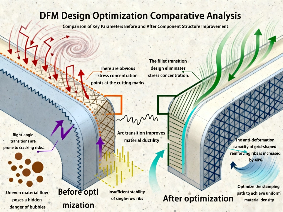
Laser Cutting Design Guide
The goal of this design guide is to ensure that structural parts possess a complete logical chain of “cuttable, bendable, weldable, and assemblable” before entering actual production. The core concept is: a small 1 mm adjustment during the design stage can often prevent costly rework in five subsequent manufacturing processes, saving both time and costs in mass production.
The following guidelines are summarized based on multiple material types and mass-production scenarios and can be directly applied to design optimization for industrial equipment, cabinets, electrical structural components, battery trays, and bracket-type parts.
Laser Cutting DFM Support and Engineering Collaboration
For customers, truly valuable laser cutting service has never been simply that the factory receives the drawing and then directly performs laser cutting according to the drawing.
What is needed is that the factory must be able to predict risks before production begins, reduce rework rates, and reserve clear allowances for subsequent processes such as bending, welding, and assembly.
Internally, we call this system pre-engineering collaboration. Its main purpose is to reduce the number of customer design iterations and ensure that prototypes can smoothly transition into mass production.
Design Review and Manufacturability Check
Before each CAD file enters production, the SR MFG engineering team conducts a DFM review, rather than only checking whether dimensions are complete and compliant.
During the review process, we focus on the following types of structures:
-
Checking the relationship between small hole size and sheet thickness.
-
Suggestions for bridging positions and structural stability.
-
Spacing, rib structures, stiffeners, and strength assessment.
-
Path-optimization suggestions for openings such as cooling slots and ventilation holes (mainly for cabinets, server panels, and electrical enclosures containing large numbers of vents).
-
Cutting-transition recommendations for assembly / bending / welding.
Real-time Engineering Support
DFM review is not a one-time action, but a support system throughout the entire project.
When we receive CAD files, we perform the following tasks to ensure that the product does not encounter excessive unexpected issues during mass production.

1. CAD File Review
After receiving the CAD file, we check:
-
Confirmation of thickness, material, and bending direction
-
Functional surface identification (assembly surfaces, datum holes, sealing grooves, etc.)
-
Manufacturability assessment of the structure (sharp corners, narrow slots, inner-corner radii)
-
Dual confirmation through automatic unfolding and manual comparison
The goal of the review is to ensure that the drawing already conforms to manufacturable logic before entering production, rather than making emergency corrections right before cutting.
2. Prototype Verification
During the prototype stage, all DFM recommendations are verified again, producing a “process reference part” suitable for batch manufacturing.
-
Compare key dimensions using a CNC measuring instrument
-
Check whether bending angles meet expectations
-
Verify whether the welded structure meets assembly requirements
-
Record surface quality and edge quality
3. Process Risk Identification
During OEM mass production of products, identifying potential risks in advance and reducing costs is extremely important.
We establish a risk matrix according to part type, including:
-
Warping risk caused by high heat input
-
Structural instability risk caused by large-area slotting
-
Process-compensation variation caused by differences between material batches
-
Magnification of accumulated dimensional errors across multi-process chains
Before mass production, our engineering team provides corresponding solutions, such as:
-
Re-arranging toolpaths
-
Fixture-assisted positioning
-
Reserving bending compensation
-
Optimizing local thickness or adding transition zones
This type of pre-risk control can significantly reduce potential issues before the product enters mass production, ensuring a more stable and controllable production process, and reducing additional costs caused by rework or process abnormalities.
Traceability, Certification, and Compliance
The following sections describe our structured approach to traceability and compliance systems.
Full Material Traceability
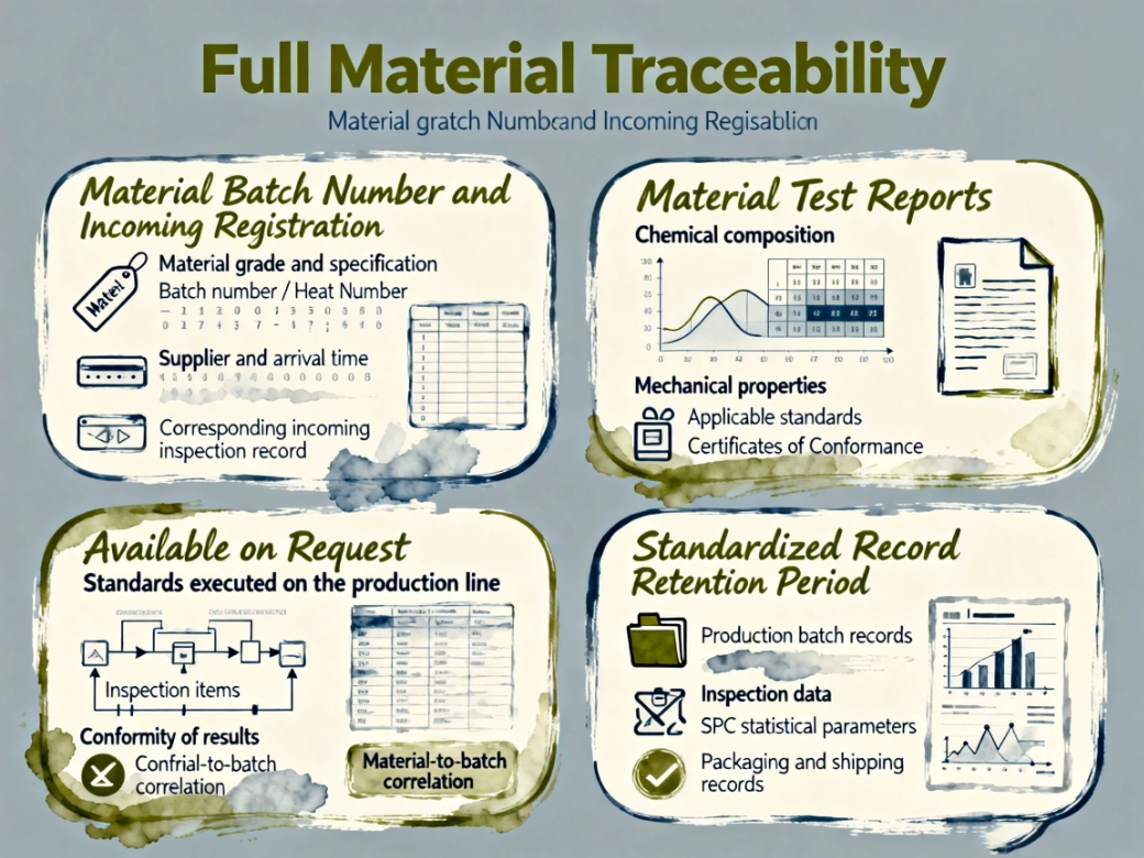
Material Batch Number and Incoming Registration
After all materials enter the warehouse, we record:
-
Material grade and specification
-
Batch number / Heat Number
-
Supplier and arrival time
-
Corresponding incoming inspection record
These data are synchronized to SR MFG’s internal system so that every part can be traced to its source batch.
Material Test Reports
Material test certificates (MTC) can be provided for carbon steel, stainless steel, aluminum, etc., including:
-
Chemical composition
-
Mechanical properties
-
Applicable standards (such as ASTM, EN, GB equivalents)
Certificates of Conformance Available on Request
When a customer project requires strict outbound auditing, a CoC can be attached to the batch to indicate:
-
Standards executed on the production line
-
Inspection items
-
Conformity of results
-
Material-to-batch correlation
Standardized Record Retention Period
To meet regulatory requirements of different countries and industries, the retention period typically covers:
-
Production batch records
-
Inspection data (FAI / in-process inspection / final inspection)
-
SPC statistical parameters
-
Packaging and shipping records
Production Certification
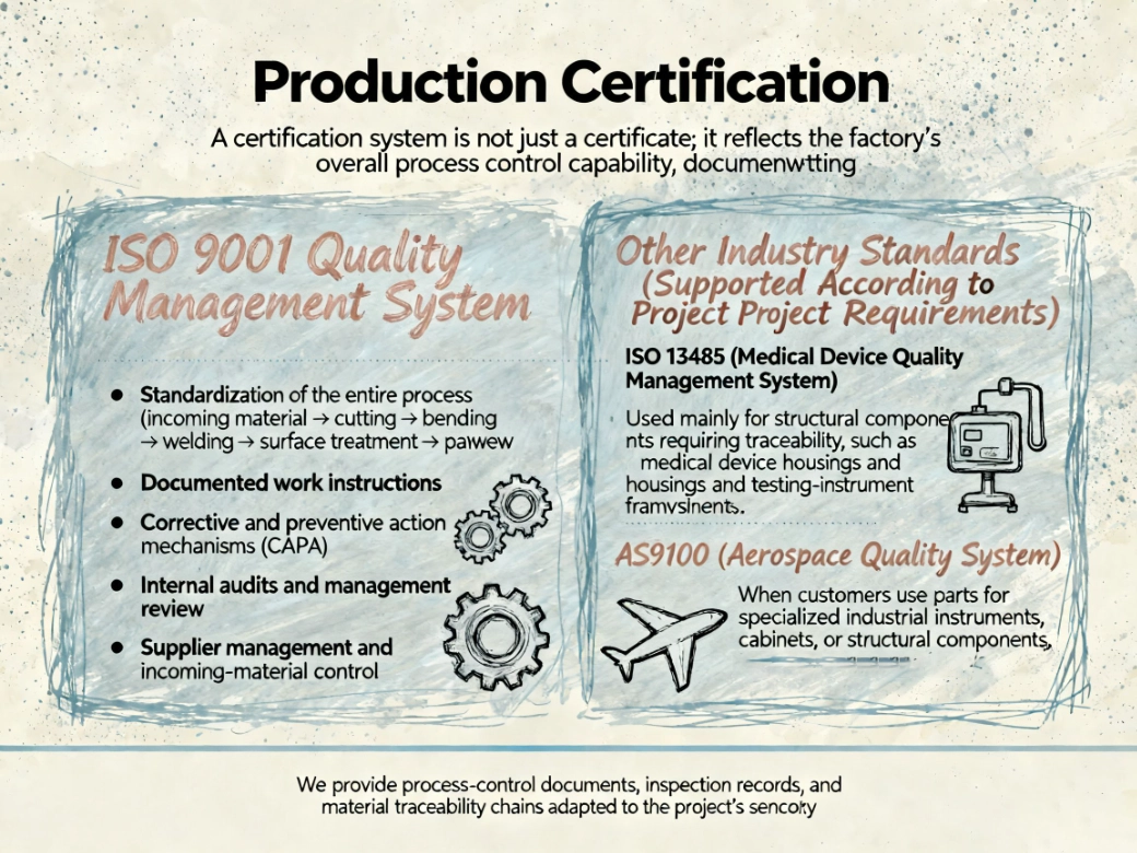
ISO 9001 Quality Management System
The factory is ISO 9001 certified, covering:
-
Standardization of the entire process (incoming material → cutting → bending → welding → surface treatment → packaging)
-
Documented work instructions
-
Corrective and preventive action mechanisms (CAPA)
-
Internal audits and management review
-
Supplier management and incoming-material control
Other Industry Standards (Supported According to Project Requirements)
Although not required for all projects, the following standards may apply to certain overseas customers:
ISO 13485 (Medical Device Quality Management System)
Used mainly for structural components requiring traceability, such as medical device housings and testing-instrument frames.
AS9100 (Aerospace Quality System)
When customers use parts for specialized industrial instruments, cabinets, or structural components, the factory can accommodate the requirements for high precision and strict traceability.
We provide process-control documents, inspection records, and material traceability chains adapted to the project’s sensitivity.
Regulatory and Export Compliance
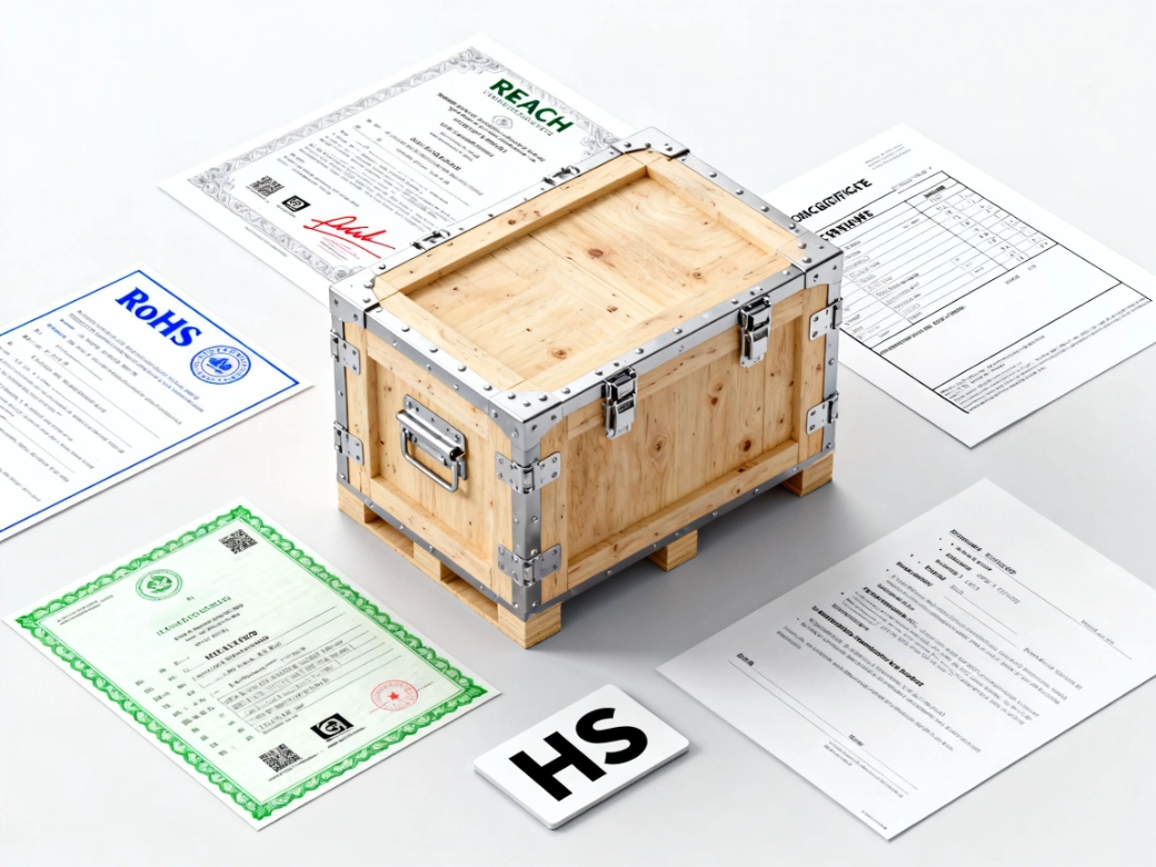
RoHS and REACH Compliance
For metal parts used in electronics, electrical equipment, server cabinets, and industrial control systems, we can provide:
-
RoHS statements for restricted and prohibited substances
-
REACH SVHC (Substances of Very High Concern) compliance statements
-
Corresponding compliance documents for surface-treatment processes (such as powder coating, galvanizing, electrophoresis, etc.)
These documents guarantee that parts meet regulatory requirements, ensuring smooth entry into EU and North American markets, meeting export standards and compliance regulations.
DFARS / Country-of-Origin Requirements (Provided on Request)
Relevant supply-chain origin documents can be provided when needed.
Export Packaging and Logistics Standards for Overseas Customers
Export packaging affects not only transportation safety but also whether parts can be put directly into production after arrival:
-
Custom wooden crates or steel frames to prevent thin sheets from being compressed or deformed
-
Anti-corrosion treatment / moisture-proof packaging suitable for sea transport and long-term storage
-
Added separation layers between parts to reduce abrasion damage
-
Providing HS Code, packing list, certificate of origin, and inspection documents according to customer needs
These standards ensure that customers do not need secondary processing during overseas warehousing, transfer, or assembly.
Laser-cut products designed and manufactured by SR MFG
SR MFG has collaborated with global OEMs to co-design and manufacture a variety of custom sheet metal products, covering enclosures, chassis, panels, brackets, and structural components.
