Partner with Shuangrui to reduce manufacturing costs by 30% and boost efficiency.

Metal Deburring Services2026-06-03T09:19:14+00:00

Metal Deburring Services

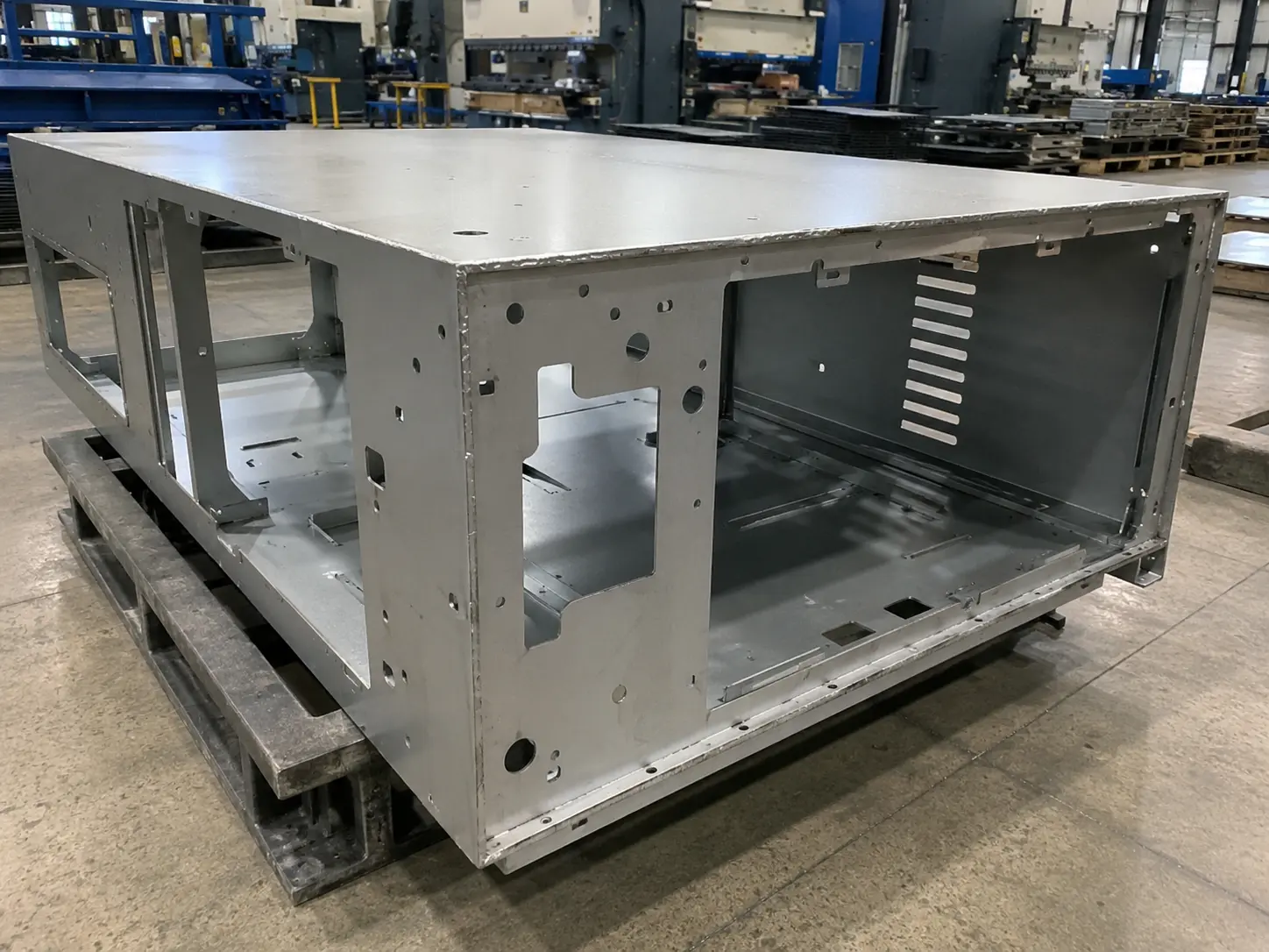
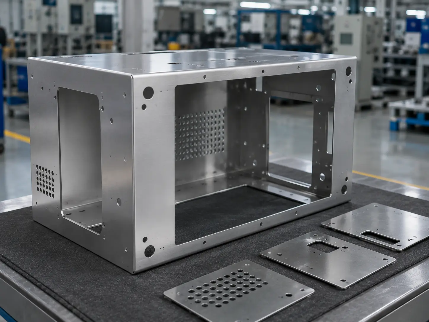
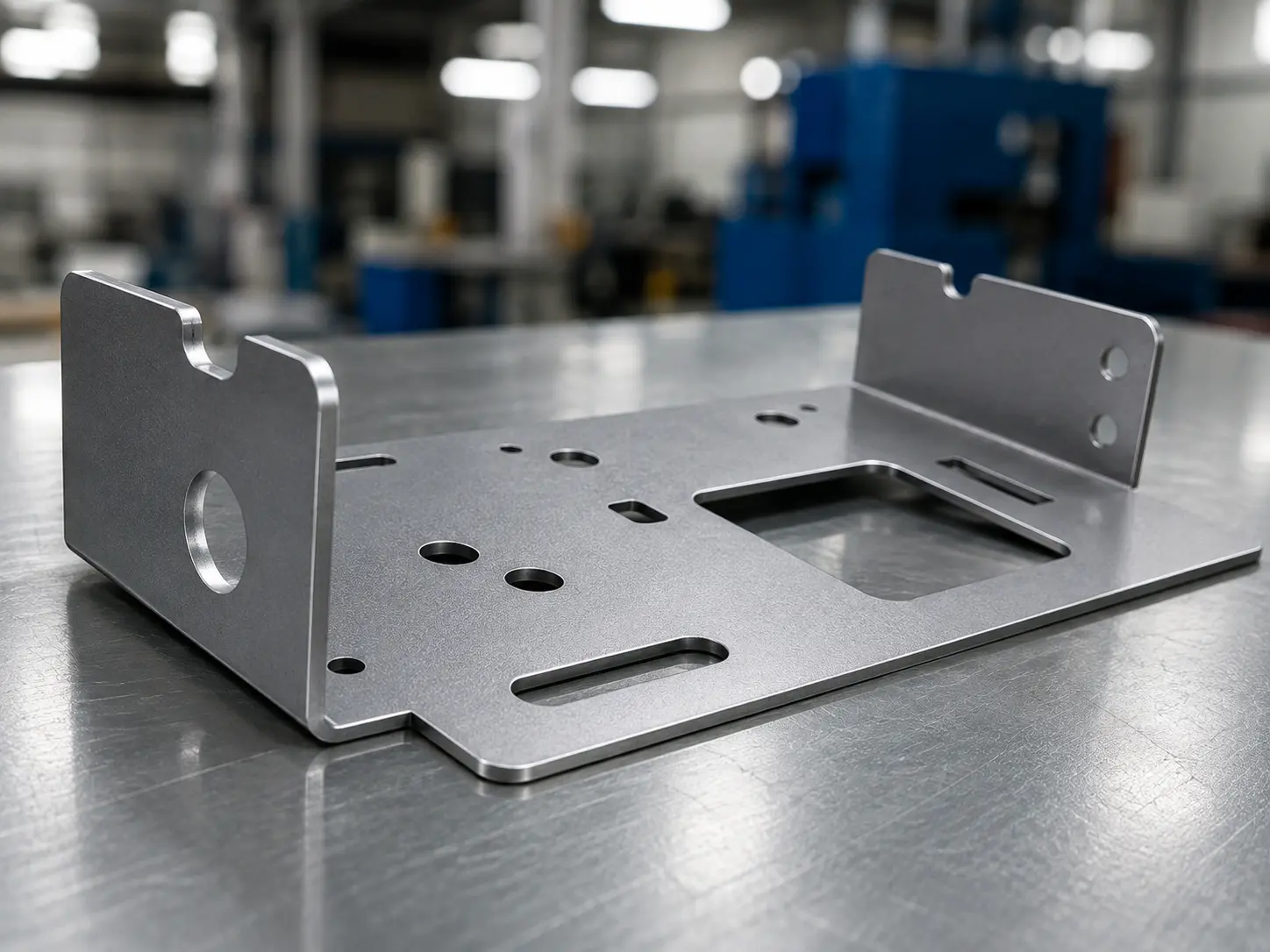
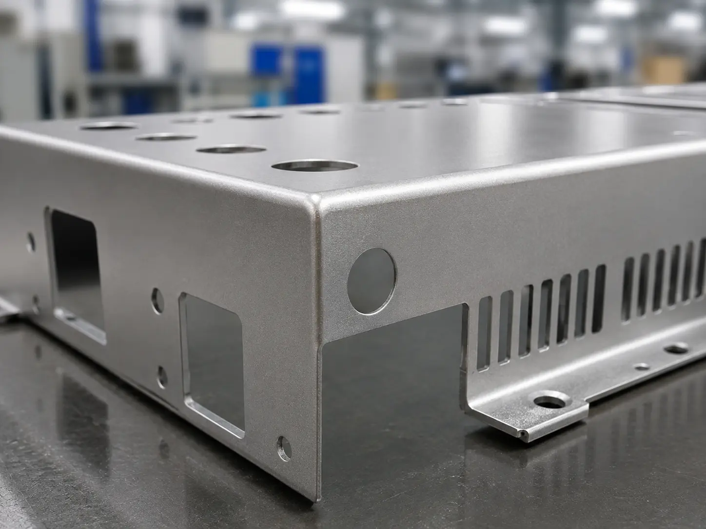
SR MFG provides standardized metal deburring services for laser-cut, stamped, and machined sheet metal parts. We remove burrs, sharp edges, dross, and defined edge conditions to improve handling safety, assembly fit, coating coverage, and final part consistency.

For critical parts, we can follow drawing-defined edge break, chamfer, radius, sample burr level, or downstream coating requirements to help your parts move smoothly into assembly, painting, plating, or shipment.
Burr Removal
Edge Break
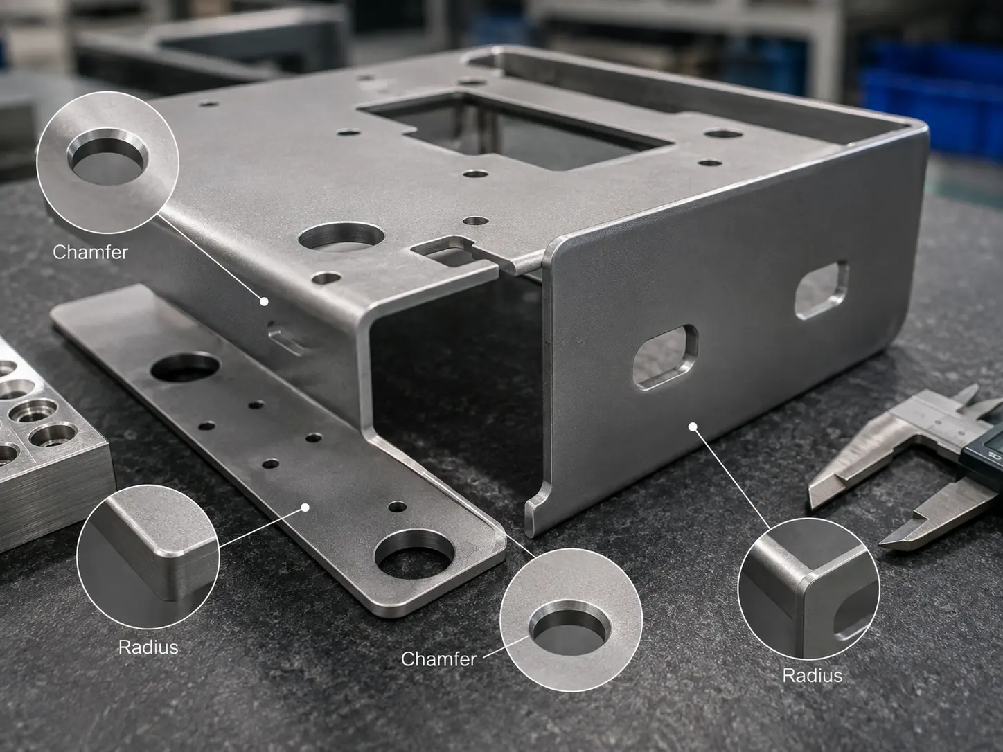
Chamfer / Radius
Dross Removal
Coating-Friendly Edges
Assembly Safety

Get a Custom Quote in 12 Hours

Upload your drawings for engineering review.

Blank Form (#4)

Why Deburring Is Essentialfor Metal Parts

Deburring removes burrs, sharp edges, and raised material left aftercutting or forming-improving safety, fit-up, coating quality, and part reliability.

Safer Handling
  • Reduces sharp edges that can cut operators
  • Improves handling during assembly and packing
  • Helps lower rework risk
Better Assembly Fit
  • Removes interference at cut edges
  • Helps parts align and fit more smoothly
  • Supports repeatable installation
Coating-Friendly Edges
  • Improves powder coating and paint edge coverage
  • Reduces thin-film risk on corners
  • Supports a cleaner finished appearance
Longer Service Life
  • Reduces stress concentration at sharp transitions
  • Can improve sealing and durability
  • Helps parts perform more reliably

Engineering Note: The right deburring method depends on material, edge requirement, downstream finish, and assembly function.

Edge Quality
Assembly Readiness
Surface Protection

What Edge Conditions Can SR MFG Deliver?

After processes such as laser cutting. stamping. machining. or welding. metal edges often end up with burs, dross, or sharp corners.Edge requirements vary widely by product-there is no single “default” condition. Below are SR MFG’s core edge-finishing capabiities

Before Before deburring edge condition
After After deburring edge condition

Complete Burr Removal

We can remove burrs down to the ~0.01 mm level. By combining multiple deburring methods as needed, we evaluate feature accessibility for cross holes, deep slots, blind cavities, and required edge acceptance criteria.

The result is no visible burrs and a smooth, snag-free feel by touch.

Edge Finishing Options

1

Burr-Free Edge

Burr-free edge finishing

Removes visible burrs and sharp raised material from cut, punched, stamped, or machined edges.

Best for: handled parts, assembly parts, cosmetic panels.
2

Edge Break

Edge break deburring

Slightly dulls sharp corners while keeping the original part geometry nearly unchanged.

Best for: safety, fit-up, and general production parts.
3

Chamfer / Radius

Chamfer and radius edge finishing

Creates a defined chamfer or radius when the drawing requires controlled edge geometry.

Best for: mating parts, covers, brackets, and precision assemblies.
4

Coating-Ready Edge

Coating-ready edge finishing

Improves edge condition before powder coating, wet painting, plating, or e-coating.

Best for: better edge coverage and lower coating failure risk.

Engineering Note: The right edge condition depends on material, edge requirement, downstream finish, and assembly function. We follow drawings, samples, or your edge quality standards.

Edge Quality
You Can Specify
Consistent
Process Control
Reliable for
Assembly & Coating

How to Select the Right Deburring Method

Different burr types. part geometries, and downstream requirements call for different deburring routes.
Review the best-fit process based on feature access, production volume, and edge-quality goals.

1

Manual Deburring

Best fit:

Low volume, high value, local touch-up

Burr type:

Accessible edges and hole mouths

Advantages:

Flexible, controllable, highly adaptable

Limitations:

High labor cost; low throughput; operator-dependent consistency

Typical uses:

Precision mating parts, prototypes, small batches

2

Mass Finishing
(Vibratory / Tumbling)

Best fit:

Small parts in volume; light overall removal acceptable

Burr type:

General external-edge burrs; light edge rounding needed

Advantages:

High batch efficiency; mature process; good consistency

Limitations:

Limited for masked areas, deep holes, or root burrs; possible part-to-part dings

Typical uses:

Hardware, standard parts, small stampings

3

Blast Deburring
(Dry / Wet / Micro)

Best fit:

External surfaces; cosmetic uniformity required

Burr type:

Fine burrs; edge break; surface cleanup

Advantages:

Can combine cleaning with appearance uniformity

Limitations:

Less effective on heavy burrs; surface damage and media residue must be controlled

Typical uses:

Cosmetic parts, casting cleanup, precision small parts

4

Electrochemical
Deburring (ECD)

Best fit:

Complex geometry; internal features hard to access

Burr type:

Cross holes, internal passages, deep slots

Advantages:

Highly selective; excellent reach; typical cycle 10–30 s

Limitations:

Requires fixtures, electrodes, chemistry control, rinsing, and corrosion control

Typical uses:

Valve bodies, pump housings, hydraulic components, cross-hole burrs

5

High-Pressure Water-Jet

Best fit:

High cleanliness requirements; want deburr + clean

Burr type:

Flash, burrs, chip residue

Advantages:

Integrated cleaning; capable up to ~245 MPa class

Limitations:

High equipment and water-treatment cost; drying and corrosion prevention required

Typical uses:

Automotive parts, engine components, precision castings

6

Ultrasonic-Assisted
Micro-Deburring

Best fit:

Precision small parts; surface-damage sensitive

Burr type:

Micro-burrs, often requiring magnification

Advantages:

Gentle on surfaces; effective for micro-burrs

Limitations:

Limited on heavy or strongly attached burrs; needs validation

Typical uses:

Semiconductor, optical, and medical precision parts

7

Thermal Energy
Method (TEM)

Best fit:

Internal features not mechanically reachable; micro-burrs or flash

Burr type:

Holes, cross passages, complex cavities

Advantages:

Effective on micro-burrs in inaccessible areas

Limitations:

Requires strict process control and post-clean verification; not suitable for all parts

Typical uses:

Multi-port components, complex internal channels

Engineering Note: Final deburring method selection should be confirmed by material, burr location, part geometry, target edge condition, downstream coating or assembly needs, and sample validation.

Discuss Your Part
Materials and Part Types We Can Deburr

Different materials and geometries require different deburring routes. We review material grade,
burr location, edge requirement, and downstream finishing before selecting the process.

Materials We Commonly Process

Carbon Steel / SPCC

Standard capability

Requires rust prevention after deburring or cleaning.

Stainless Steel

Standard capability

Avoid free-iron contamination; suitable for visible and corrosion-resistant parts.

Aluminum Alloys

Standard capability

Soft and easy to scratch; use controlled media and handling.

Galvanized Steel

Use gently

Use gentle deburring to protect the zinc layer.

Copper & Copper Alloys

Use gently

Prone to oxidation and fingerprints; may need protective packaging.

Common Part Types We Deburr

Flat sheet-metal cut parts

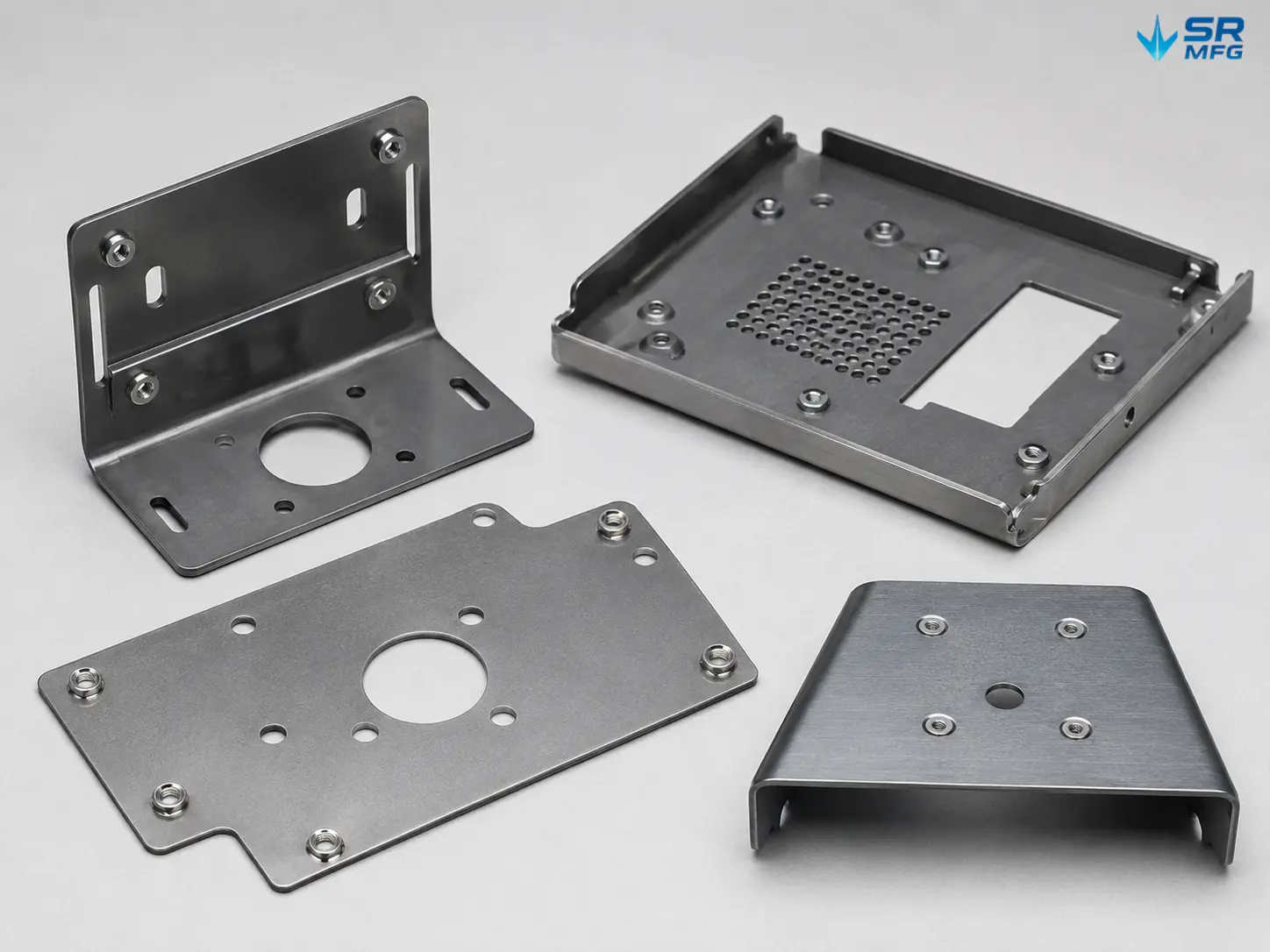
Panels, brackets, mounting plates, heat sinks, separators.

Bent and formed parts

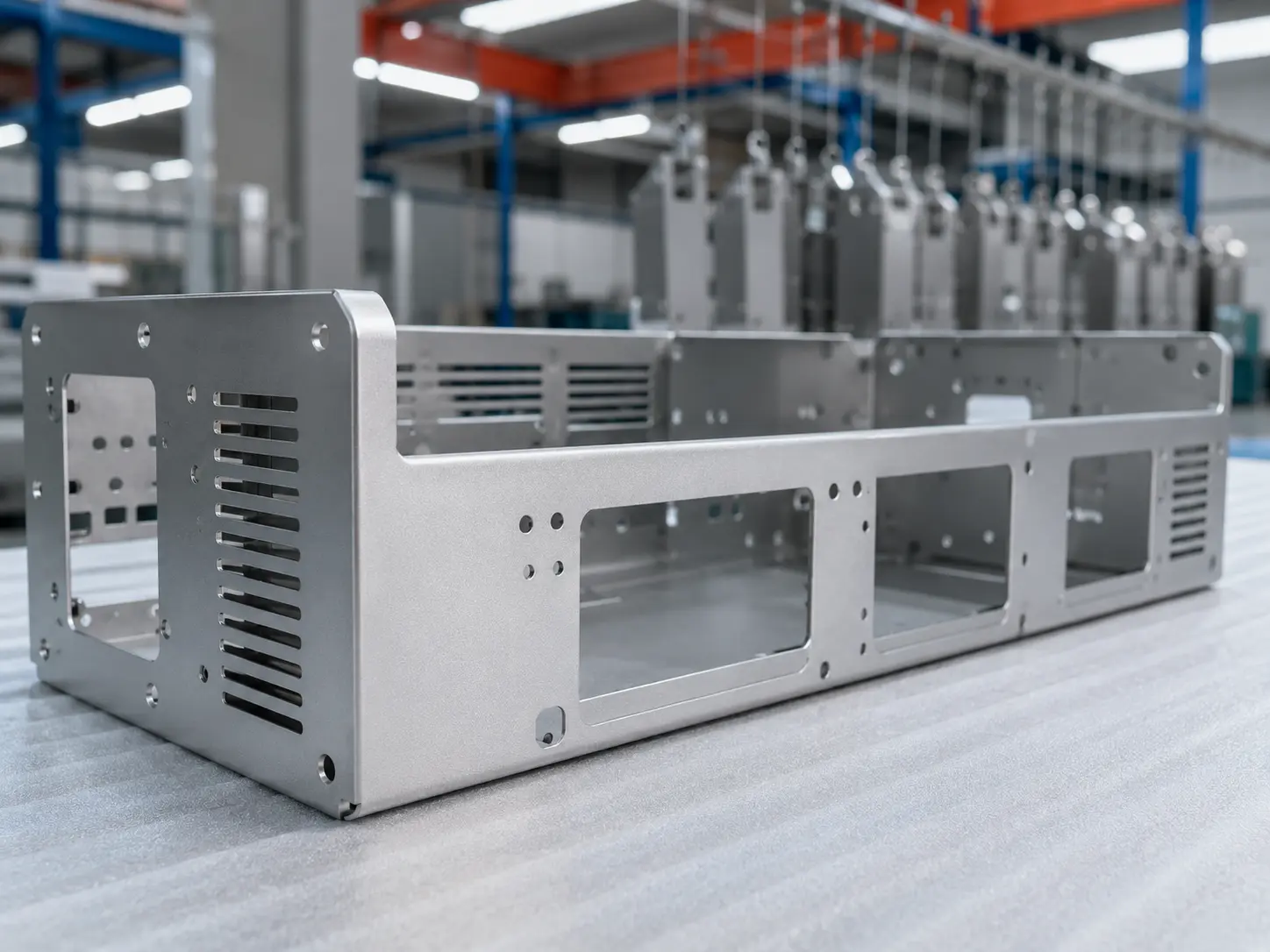
Enclosures, covers, U-brackets, L-brackets, cosmetic panels.

Stampings and small hardware

Clips, spring tabs, washers, terminals, perforated parts.

Machined edges and hole mouths

Drilled/tapped holes, slots, step edges, small features.

Weldments and transition zones

Welded brackets, frame assemblies, edge-transition areas.

Engineering Note: Final deburring route should be confirmed by material, burr location, part geometry, target edge condition, downstream coating or assembly needs, and sample validation.

Material
Review
Edge
Requirement
Assembly
Readiness
Explore the SR MFG Material Library

Standardized Deburring Process Flow

Metal Deburring Process (Video Showcase)

1

Drawing & Edge Review

  • Confirm drawing, edge standard, and acceptance criteria
  • Define burr condition, radius, or edge break requirement
2

Incoming Inspection & Traceability

  • Check part status and batch identity
  • Set traceability before processing
3

Cleaning & Area Protection

  • Remove oil, chips, and loose residue
  • Mask critical or cosmetic areas when required
4

Primary Deburring Operation

  • Apply the selected deburring process route
  • Control consistency, removal amount, and edge form
5

Edge Verification & IPQC

  • Verify burr removal and target edge condition
  • Inspect fit-up, handling safety, and cosmetic quality
6

Final Cleaning, Packaging & Shipment

  • Clean and dry parts after processing
  • Use protective packaging for delivery

Engineering Note: Actual deburring flow depends on material, burr location, target edge condition, part geometry, downstream coating or assembly needs, and sample validation.

Edge Quality
Inspection Control
Delivery Protection

Are you ready to get started on your metal fabrication project?

Not sure which material is ideal for your project? Feel free to contact us.Our engineering team will recommend suitable material grades and sheet thicknesses based on strength, weight, corrosion resistance and overall cost.

Metal Deburring FAQs​​​​

Not always. Whether an edge feels “non-cutting” depends on the deburring method and, more importantly, the acceptance criteria. In practice, if burr height is controlled to roughly 0.05–0.2 mm, many applications will consider it acceptable for handling—but the final requirement should be whatever your drawing/spec defines. A common quick check is the cotton-glove test: lightly run a cotton glove along the edge; no snagging or catching is used as a practical screening method, while final disposition still follows the specified standard.

Most internal-hole and internal-cavity burrs can be addressed, but the correct process depends on hole diameter, depth (L/D ratio), and overall geometry complexity.

A practical “five-step accessibility check” is:

  1. Extract key geometry from the 3D model/drawing: minimum entry size, depth/L-D ratio, maximum cavity clearance, cross-hole locations.

  2. Physical reachability assessment: confirm whether tools/media/electrodes can enter and act stably on the target edge.

  3. Process-route selection: choose different routes for external edges vs. internal channels/cross holes (evaluate options such as ECD or TEM when needed).

  4. Inspection method definition: visual inspection, borescope, sectioning, weight-loss methods, or other feasible verification (project-dependent).

  5. Trial validation: run deburring tests on actual parts (or representative 3D-printed samples) and approve a reference sample for production.

It can, but the impact is typically small and controllable, often at the micron level, provided the process window and edge requirement are defined and managed.

In most cases, yes. Deburring is inherently a contamination-generating step and can leave new residues (chips, abrasive media, dust). A post-deburr cleaning and drying step is commonly required to ensure downstream coating/assembly reliability.

A widely used approach is ISO 13715:2017 (Technical product documentation — Edges of undefined shape — Indication and dimensioning). It reduces ambiguity and aligns design, manufacturing, and inspection.

Core symbol logic (simplified):

  • “+”: material excess permitted (e.g., burr/rollover allowed)

  • “−”: material removal required (deburr/edge clean-up required)

  • “±”: either material excess or removal permitted

Example: deburr required on an external edge (precision part)
Ⓤ − 0.05
Meaning: for the specified external edge (Ⓤ), material removal is required, and the maximum allowed removal is 0.05 mm. In other words, burrs must be removed completely, but the resulting chamfer/edge removal must not exceed 0.05 mm.

Metal Deburring Technical Resources

Go to Top