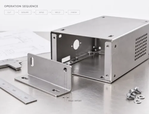
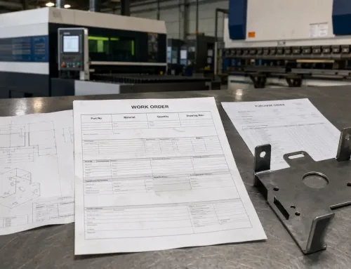
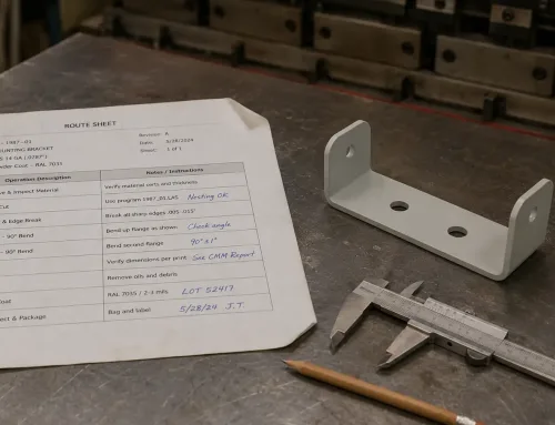
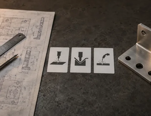
A process flow is the sequence of steps used to turn raw material into finished parts. In the sheet metal manufacturing process, it covers every operation from design review and material sourcing to cutting, bending, welding, surface finishing, inspection, and delivery, arranged in the order in which they actually occur.
Each step has clear inputs, outputs, and decision points. For B2B teams evaluating suppliers, requesting quotes, or managing production, understanding a sheet metal manufacturer’s process flow is one of the most direct ways to assess its manufacturing capability, cost structure, and delivery reliability.
What Is a Process Flow?
A process flow describes which operations a part goes through, in what sequence, and under what conditions. A simple way to understand it is through the model:
Input → Process → Output
When sheet metal enters a factory system, it goes through a series of value-added operations and eventually leaves as finished custom sheet metal parts, ready for assembly or shipment.
It is important to distinguish between a process flow and a process flow diagram. A process flow is the actual sequence of operations that takes place. A process flow diagram, or PFD (Process Flow Diagram), is a visual or written document used to represent that sequence.
The process exists whether it is documented or not. However, only when the process is recorded can it be analyzed, improved, and consistently repeated.
Process Flow vs. Workflow vs. Flowchart
These three terms are often used interchangeably in manufacturing, but they refer to different levels of scope.
| Term | Scope | Typical Use |
|---|---|---|
| Process Flow | The complete manufacturing sequence for a part or product family | Strategic planning, quotation, supplier evaluation |
| Workflow | Task-level movement, often in digital form — who does what, when, and in which system | Project management, ERP/MES configuration |
| Flowchart | A visual representation of the process flow, often used for analysis and improvement | Lean activities, root cause analysis |
In a manufacturing environment, the process flow is the backbone. Workflows and flowcharts are supporting tools built around it.
Why Process Flow Matters
Standardization and Repeatability
A documented process flow ensures that every shift, every operator, and every production site manufactures parts according to the same standard. Without it, manufacturing knowledge exists only in individual memory, which is fragile, inconsistent, and invisible to customers.
Cross-Functional Alignment
A shared process flow gives engineering, production, quality, and purchasing teams a common reference point. When a customer asks, “How is this part made?”, the answer is clear and consistent. When an engineering change is proposed, its impact on downstream operations can be evaluated before implementation.
Foundation for Continuous Improvement
You cannot improve what you cannot see. A documented process makes bottlenecks, redundant steps, and rework loops visible. It turns abstract goals such as “reduce cost” or “shorten lead time” into specific, actionable improvement projects. This is the starting point for lean manufacturing and continuous improvement.
Key Elements of a Process Flow
Process Steps and Sequence
Every process flow consists of discrete steps arranged in a specific order. The sequence may be:
Linear — Step A, then Step B, then Step C
Parallel — Step A and Step B happen at the same time before moving to Step C
Conditional — If a part fails inspection at Step B, it enters rework and then returns to Step C
Inputs and Outputs at Each Stage
Each step consumes inputs, such as a semi-finished part, raw material, energy, or tooling, and produces outputs, such as a cut blank, a bent component, or a welded assembly.
Clearly defining these input-output relationships is essential if the process flow is to be used for cost estimation and production scheduling.
Decision Points and Inspection Gates
Not every step is a simple transformation. A decision point, usually represented by a diamond in a flowchart, asks a question:
Is this dimension within tolerance?
Is the weld acceptable?
The answer determines whether the part moves forward, enters rework, or is scrapped. These inspection gates show exactly where quality control is embedded into the production logic.
Standard Symbols and Conventions
Most process flow diagrams use a common visual language:
- Oval — Start or end point
- Rectangle — Process step or operation
- Diamond — Decision or inspection point
- Arrow — Process direction
These symbols come from widely used flowchart conventions, including common symbols for start/end points, operations, decisions, and flow direction. In practice, companies may adjust them based on internal documentation standards or customer requirements.
Roles and Responsibilities
A complete process flow should identify who is responsible for each step. This means not only which machine performs the operation, but also which role, such as an operator, inspector, or engineer, makes decisions and signs off on the result.
This is especially important in regulated industries such as aerospace and medical devices, where traceability to specific personnel may be required.
Sheet Metal Manufacturing Process Flow: Step-by-Step Overview
The following example is based on the sheet metal manufacturing process flow at SR MFG. Actual steps may vary depending on part geometry, material, tolerance requirements, order volume, and customer specifications.
Stage 1 — RFQ Review, DFM Analysis, and Quotation
The process begins before any metal is cut. After receiving the customer’s technical drawing or 3D model, SR MFG conducts a Design for Manufacturability (DFM) review.
Key questions include:
- Can the required bend radius be achieved?
- Are the tolerances reasonable for the selected material and process?
- Can the part be nested efficiently on the sheet?
DFM feedback at this stage can lock in or release significant advantages in cost, lead time, and production stability later in the process.
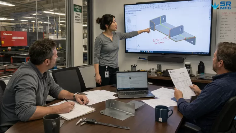
A DFM review session before quotation — engineers evaluate bend radius, tolerances, and nesting efficiency on a 3D CAD model, with a physical sample and annotated drawing on the desk
Stage 2 — Material Selection and Sourcing
Based on the engineering specifications, the appropriate sheet material is selected, including metal grade and thickness selection, temper or condition, and surface quality.
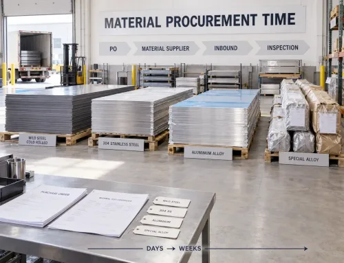
Material availability directly affects when production can begin. For purchasing teams, this is a common source of lead time variation that must be tracked carefully.
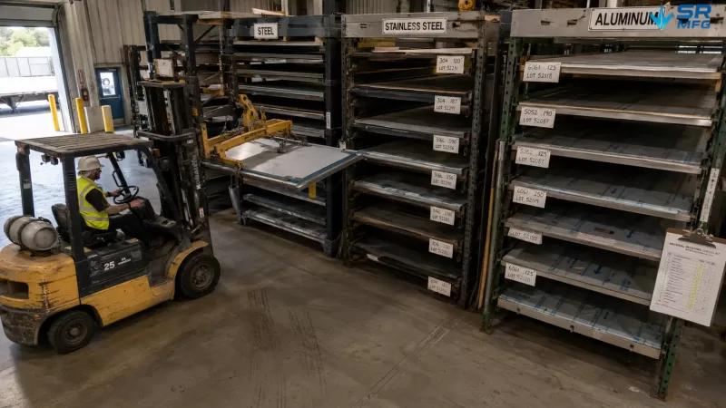
Raw material storage racks organized by alloy grade and sheet thickness — material availability is a critical prerequisite for starting the production process flow
Stage 3 — Cutting and Blanking
Flat sheet metal is cut into the required profile. The method depends on geometry complexity, material thickness, production volume, and edge quality requirements.
- Laser cutting — High precision, suitable for complex geometries and thin to medium-thickness sheet metal
- Punching / turret punching — Fast and cost-efficient for standard features such as holes, louvers, and formed details in high-volume parts
- Shearing — Simple straight-line cutting for basic rectangular blanks
- Waterjet cutting — No heat-affected zone, suitable for thick plates or heat-sensitive materials
Nesting, or arranging parts efficiently on a sheet to maximize material utilization, is a key optimization method at this stage.
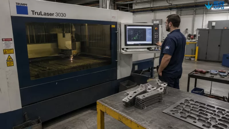
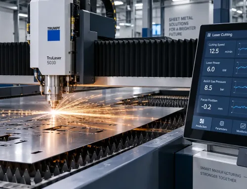
A fiber laser cutting machine processes a nested sheet of steel brackets — the operator monitors cutting progress on the HMI screen while finished parts and skeleton scrap accumulate on the unloading table
Stage 4 — Forming and Bending
Cut blanks are formed into three-dimensional shapes through sheet metal bending on a press brake.Bend sequence planning is critical because the order of bends affects feasibility, accuracy, and whether custom tooling is required.
Springback compensation, tooling selection, including punch radius and die opening width, and back gauge programming are all completed during this stage.
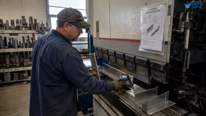
Press brake work area after a completed bend — the digital angle readout shows 90.1°, back gauge fingers hold position, and color-coded punch and die sets hang on the wall tooling rack
Stage 5 — Joining and Assembly
Multiple formed parts may be joined through different methods, including:
- Welding — MIG, TIG, spot welding, or laser welding; commonly used for structural parts
- Riveting and hardware insertion — Including self-clinching nuts and PEM inserts; suitable for removable assemblies or parts that are not ideal for welding
- Adhesive bonding — Used in specific applications that require vibration damping or joining of dissimilar materials
Fixture design is especially important at this stage because it helps maintain correct part positioning during joining.
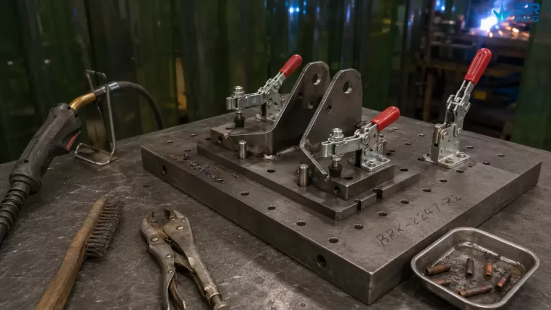
A custom welding fixture positions two formed brackets using machined locating pins and manual toggle clamps — the MIG welding gun waits on its hook while the operator prepares to begin the weld
Stage 6 — Surface Finishing
Depending on the application, parts may go through one or more sheet metal surface finishing processes.
- Deburring and grinding — Removes sharp edges and weld spatter
- Powder coating and liquid painting — Provides corrosion protection and improves appearance
- Anodizing for aluminum, passivation for stainless steel, and galvanizing for carbon steel
Masking requirements, such as protecting specific surfaces or holes from coating, usually need to be considered earlier in the planning stage and reflected in the process flow.
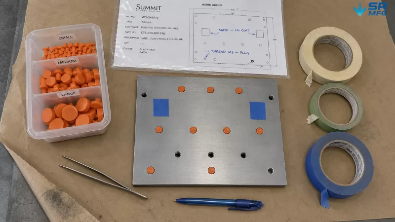
Powder coating masking preparation — silicone plugs seal threaded holes and tape protects mating surfaces, guided by a work order specifying exactly which features must remain uncoated
Stage 7 — Quality Inspection and Testing
Inspection takes place throughout the process. A complete final inspection stage may include:
- Dimensional verification using CMMs, calipers, gauges, or go/no-go gauges
- Visual inspection for scratches, dents, coating defects, and other appearance issues
- Functional testing, such as fit checks or pressure testing, when required
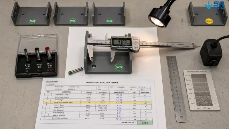
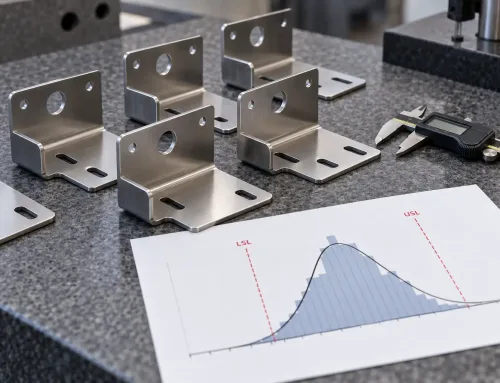
A quality inspection station with a digital caliper measuring a critical bracket dimension, go/no-go pin gauges testing hole diameters, and a completed inspection report recording all measured values
For critical applications, such as aerospace, medical, defense, and other high-requirement industries, a formal First Article Inspection (FAI) may be required before full production, following AS9102 or an equivalent standard.
Stage 8 — Packaging, Logistics, and Delivery
The final step includes protective packaging to prevent coating or finished surface damage, labeling, shipping documentation, and traceability records.
For international shipments, customs documents and material certificates may also be required.
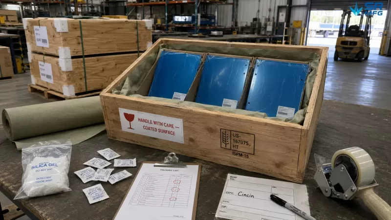
Finished parts packed in cardboard dividers inside a wooden crate, lined with VCI anti-rust paper and desiccant sachets — a handling warning label protects the coated surfaces during transit
How Materials and Design Change the Process Flow
A process flow is not a fixed template. It changes according to the technical requirements of each part, including material type, part geometry, tolerance requirements, production volume, and quality standards.
How Material Changes the Process Flow
Different materials, such as aluminum sheet, stainless steel, and carbon steel, require different cutting parameters, bend radii, and surface preparation methods.
For example, aluminum has lower stiffness and greater springback, so it often requires over-bending compensation and careful tooling selection. Stainless steel work-hardens during forming, which may limit the number of bending operations before annealing is required. Galvanized steel can release harmful fumes during welding, so additional ventilation and safety measures must be included in the welding stage.
How Design Changes the Process Flow
Part design has a direct impact on the number and sequence of operations.
A bracket with bends in four different directions may require four separate press brake setups, while a simple part with bends in only one direction may need just one. Tighter tolerances add more inspection gates. A complex welded assembly may split the process into parallel subassembly branches that merge at the welding stage.
How Production Volume Changes the Process Flow
Production quantity can completely change how the same part is manufactured.
A prototype sheet metal order of five pieces may use laser cutting and simple bending tools, with minimal fixturing requirements. In contrast, a 10,000-piece production run may justify dedicated stamping dies, custom fixtures, and in-line inspection.
For the same part, these two scenarios can result in completely different process flows.
Quality Control Embedded in the Process Flow
Quality control is not a separate activity performed only after production is complete. It is built into specific points throughout the manufacturing process.
- Incoming material inspection — Verifies material certificates, thickness, and surface condition before raw material enters production
- In-process inspection — Checks burrs and dimensions after cutting, angles and bend radii after bending, and weld quality after welding through visual inspection, penetrant testing, or ultrasonic testing when required
- First Article Inspection (FAI) — A full dimensional and documentation review, usually performed when a new part enters production or after an engineering change
- Final inspection — Confirms dimensional accuracy, appearance quality, packaging, and documentation before shipment
When nonconforming parts are found, the process flow defines the handling path: rework, where the part is processed again; concession acceptance, where the part may be accepted with customer approval; or scrap, where the part is rejected and replaced.
This abnormal or “non-standard” path is a critical part of a complete process flow, but it is often overlooked.
How Process Flow Drives Cost, Lead Time, and Purchasing Decisions
Process Steps Are Cost Drivers
Every step in the process adds cost, including machine time, labor, consumables, and management overhead.
A part that passes through eight operations will usually cost more than a part that passes through five operations, even if both use the same raw material. Understanding this helps purchasing teams determine whether a supplier’s quotation reflects real manufacturing complexity or includes inflated processing costs.
Process Complexity and Lead Time
Sequential steps extend lead time because each operation must wait for the previous one to be completed. Parallel operations can shorten lead time by allowing different tasks to happen at the same time.
Surface finishing and outsourced processes, such as special coatings or heat treatment, are among the most common causes of longer lead times because they introduce external scheduling dependencies.
Supplier Process Questions Purchasing Teams Should Ask
When evaluating a sheet metal fabrication supplier, purchasing teams can ask the following questions:
- “Can you provide the process flow for this part?” — A capable supplier should be able to provide it.
- “Where are your inspection gates in the process?” — This shows how quality is embedded into the process, not merely promised.
- “Which processes are done in-house, and which are outsourced?” — In-house operations usually allow tighter schedule and quality control.
- “How do you handle nonconforming parts?” — The supplier should have a defined process, not a temporary reaction.
- “Is your process flow linked to the control plan?” — This is a sign of a mature quality control system.
Signs of Process Maturity
A well-managed fabrication shop maintains process flows that are documented, version-controlled, and linked to control plans and work instructions.
Warning signs include process knowledge being passed only by word of mouth, key process details existing only in one person’s head, and no traceability between production steps.
A mature process flow makes manufacturing more predictable, measurable, and repeatable, which is especially important for B2B buyers who care about cost control, quality stability, and reliable delivery.
Common Mistakes and Pitfalls
- Treating the process flow as a one-time document. A process flow is a living system. It must be updated when the design changes, equipment is replaced, or lessons are learned from quality issues.
- Designing only the “normal path.” Ignoring rework loops, scrap handling, and abnormal conditions makes the process incomplete and fragile.
- Too much detail or not enough detail. Recording every small hand movement of an operator creates noise. Missing a critical inspection gate creates risk. The right level of detail depends on the audience and the purpose of the document.
- Creating the process behind closed doors. A process designed only by the engineering team, without feedback from the production line, may miss real manufacturing constraints. Operator involvement is essential.
- Disconnecting the process from other documents. A standalone process flow that is not linked to the control plan, work instructions, or PFMEA has limited practical value.
Relationship Between Process Flow and Other Manufacturing Documents
A process flow does not exist in isolation. It is part of a connected manufacturing documentation system.
| Document | Scope | Used By |
|---|---|---|
| Process Flow | What happens and in what sequence | All stakeholders, including engineering, production, quality, and purchasing |
| Control Plan | What is inspected at each step, which method is used, and how often checks are performed | Quality engineers and inspectors |
| Work Instruction (WI) | Step-by-step operating guidance for a specific process | Production operators |
| Process Failure Mode and Effects Analysis (PFMEA) | Risk analysis of the process flow, including what could go wrong at each step and how it can be prevented | Cross-functional quality teams |
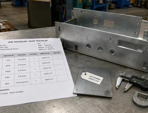
| Process Traveler / Routing Card | Shop-floor execution document used to track a specific production order through each step | Production planners and shop-floor supervisors |
The process flow is the foundation. Other documents are built on top of its structure. It defines the framework, while related documents add detailed instructions, risk analysis, inspection logic, or execution records.