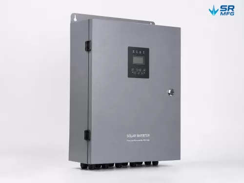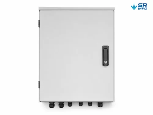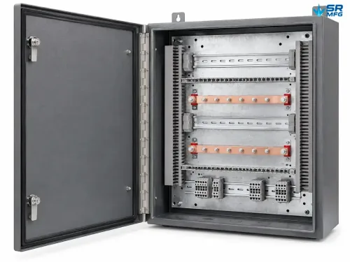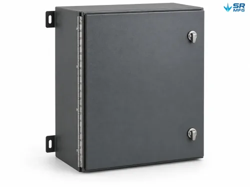
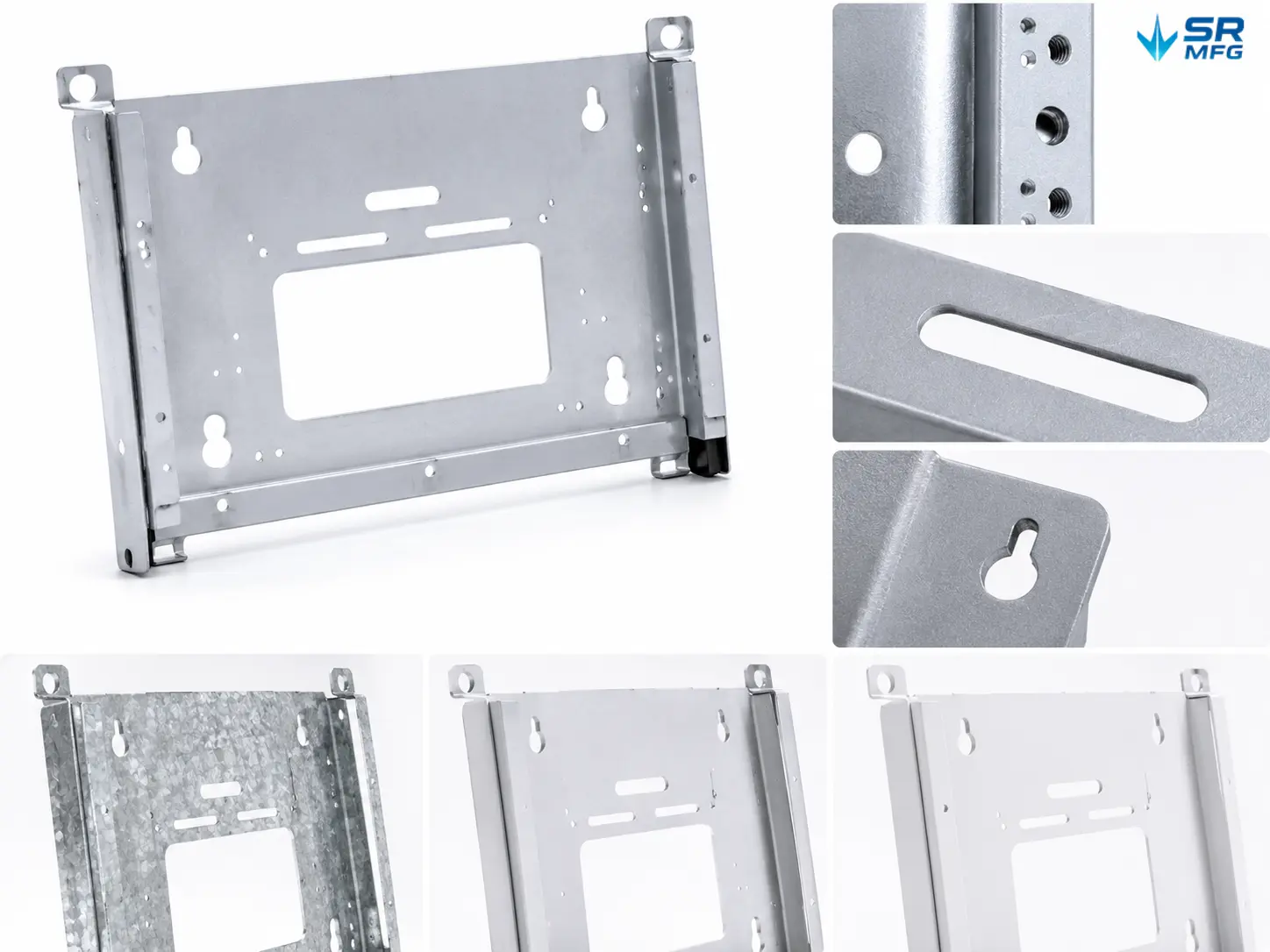
Custom Solar Inverter Mounting Brackets
We provide custom sheet metal mounting brackets for string inverters, central inverters, and microinverters. Available materials include galvanized steel, aluminum alloy, and stainless steel, with wall-mounted, pole-mounted, and ground-mounted frame configurations.· Load Capacity: Structurally designed for inverter weights from 5 kg to 150 kg
- Hole Layout: CNC-punched according to the inverter backplate drawing, with a hole-position tolerance of ±0.2 mm
- Surface Finish: Hot-dip galvanizing (≥85 μm), anodizing, or powder coating selected according to the project environment
- Thermal Management: Bracket stand-off spacing and ventilation features maintain airflow around the inverter enclosure
- Manufacturing: Send us your drawings and receive a custom quotation within 24 hours
| Process | assembly, bending, Laser cutting, stamping, welding |
|---|---|
| Surface Finish | anodizing, passivation, Powder coating |
Product Details
| Specification | Details |
|---|---|
| Base Material | Galvanized steel (Q235B / Q355B) / Aluminum alloy (6061-T6 / 6063-T5) / Stainless steel (SUS304 / SUS316) |
| Material Thickness | 1.5 mm – 6.0 mm, selected according to load requirements |
| Safe Working Load | Up to 30 kg / 60 kg / 100 kg / 150 kg, depending on mounting method and material |
| Design Wind Load | Up to 60 m/s (216 km/h) — site-specific engineering design available |
| Design Snow Load | 1.0 – 2.5 kN/m², depending on canopy angle and material |
| Hole Position Tolerance | ±0.2 mm, CNC punched or drilled |
| Stand-Off Clearance | ≥100 mm from the mounting surface as standard / Custom spacing available |
| Ventilation Open Area | ≥0.05 m² per kW of inverter rated power |
| Surface Finish — Hot-Dip Galvanizing | Hot-dip galvanized, zinc coating ≥85 μm, EN ISO 1461 |
| Surface Finish — Anodizing | Type III hard anodizing, 25–50 μm, MIL-A-8625 |
| Surface Finish — Powder Coating | Polyester / epoxy, 60–80 μm DFT, RAL colors available upon request |
| Salt Spray Resistance | Hot-dip galvanized ≥500 hours (ASTM B117) / Marine-grade configuration ≥1,000 hours |
| Operating Temperature | −40°C to +85°C |
| Fastener Specification | Stainless steel A2-70 as standard / A4-80 for marine environments, M8–M16 |
| Galvanic Corrosion Isolation | EPDM isolation pads, nylon-sleeved fasteners, anodized aluminum washers |
| Thermal Expansion Design | Slotted mounting holes at wall connection points |
| Vibration Resistance | Designed in accordance with IEC 60068-2-6 |
| Mounting Configuration | Wall mount / Pole mount for 1.5″–3″ pipe diameters / Ground-mounted frame |
| Tilt Range | Fixed at any specified angle / Adjustable from 0°–90° |
| Design Service Life | 25 years for the structure / 10-year coating warranty |
| Manufacturing Processes | Laser cutting, CNC punching, bending, welding, tapping |
| Prototype Lead Time | 7–15 working days |
| Mass Production Lead Time | 15–30 working days |
| Documentation | MTC, coating thickness report, dimensional inspection report |
Engineered for Inverter Reliability — Not Just an Ordinary Bracket
A solar inverter is the control center of a photovoltaic system. It converts DC power into AC power, manages grid synchronization, and is expected to operate continuously outdoors for up to 25 years. The bracket securing the inverter must withstand static loads, wind loads, and repeated thermal cycling without interfering with the inverter’s own heat dissipation. Otherwise, system performance may begin to degrade long before the intended service life is reached.
This product is a purpose-built inverter mounting bracket produced through custom sheet metal fabrication according to the mounting-hole pattern of your specific inverter model and the environmental requirements of your project. We manufacture wall-mounted, pole-mounted, and ground-mounted frame structures in galvanized steel, aluminum alloy, or stainless steel, with surface treatments selected to match the corrosion category of the installation site.
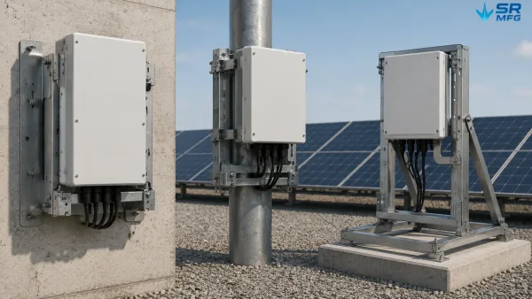
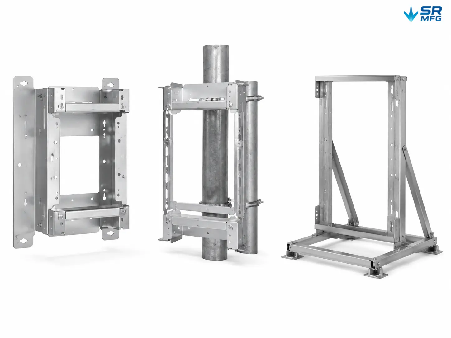
This image shows three common solar inverter mounting bracket configurations used for different installation environments.
Structural and Thermal Management Design
Most mounting bracket failures in the field can be traced back to three root causes: incorrect hole positioning, inadequate surface protection, and insufficient section modulus to withstand actual wind loads. Our engineering review addresses all three issues before manufacturing begins.
Thermal Management
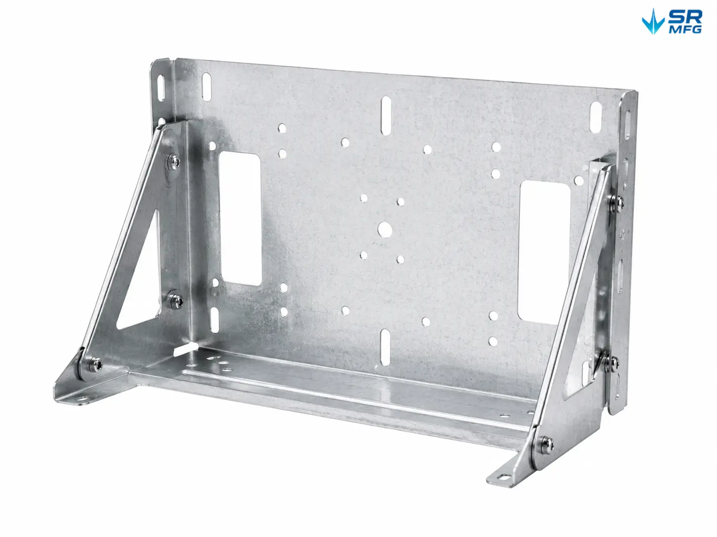
Inverters reduce their output when operating temperatures exceed specified thresholds. The bracket stand-off distance and ventilation openings must allow sufficient natural convection around the solar inverter sheet metal enclosure. For a typical 10 kW string inverter, we specify a minimum ventilation open area of ≥0.05 m² per kilowatt of rated inverter power, together with a minimum stand-off clearance of ≥100 mm from the mounting surface. For installations exposed directly to rain, louvered side panels or perforated backplates can be incorporated.
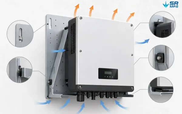
This image shows the stand-off spacing and ventilation features used to maintain airflow around the inverter.
Galvanic Corrosion Protection
When an aluminum inverter enclosure comes into contact with a steel bracket, or when a steel bracket is assembled with stainless steel fasteners, galvanic corrosion can begin within months in humid or coastal environments. For every mixed-metal configuration, we provide EPDM isolation pads, nylon-sleeved fasteners, and anodized aluminum washers as standard. These are not optional accessories; they are built directly into the overall assembly design.
Thermal Expansion Compensation
Slotted mounting holes are used at wall connection points to accommodate differences in thermal expansion between the bracket and the mounting substrate. Over a 25-year service life, with temperatures cycling between −40°C and +85°C, a 1-meter-long steel bracket can undergo approximately 2.5 mm of expansion and contraction. The slotted-hole design absorbs this movement without transferring additional stress to the anchor bolts or wall substrate.
Hole Position Accuracy
Mounting holes are CNC punched or drilled according to dimensional drawings provided by the inverter manufacturer, with a positional tolerance of ±0.2 mm. For EPC projects involving multiple inverter brands, we can manufacture bracket series for different models under the same supply program.
Three Mounting Configurations
Wall-Mounted
Suitable for building exteriors, equipment rooms, and plant-room walls. Depending on the wall structure, the bracket can be secured to concrete, masonry, or steel framing using chemical anchors, expansion bolts, or through-bolts. Standard designs can support inverters weighing up to 80 kg. For heavier equipment, reinforcement plates and additional anchoring points can be added to distribute the load over a larger wall area.
Typical application: A 20 kW string inverter weighing approximately 35 kg mounted on an exterior concrete wall in a commercial rooftop solar project. The bracket provides a 100 mm stand-off clearance for heat dissipation and includes slotted backplate holes for thermal expansion compensation.
Pole-Mounted
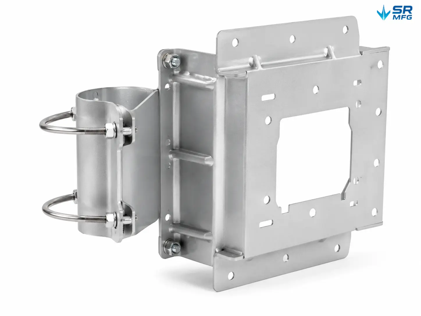
Suitable for off-grid projects, integrated solar street-light systems, and distributed ground-mounted PV arrays where wall mounting is not practical. U-bolt clamps or welded pole clamps can accommodate pipe diameters from 1.5″ to 3″. Pole-mounted brackets can support inverters weighing up to 60 kg and are engineered to withstand wind-induced vibration associated with elevated installations.
Typical application: A group of microinverters mounted to steel poles beneath a PV module array at a ground-mounted solar farm, reducing DC cable length.
Ground-Mounted Frame
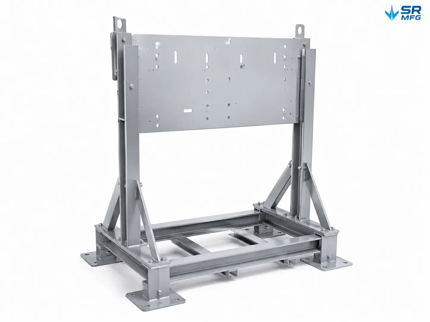
Suitable for string inverter arrays in large ground-mounted solar farms and other energy and power sheet metal applications, including auxiliary equipment for battery energy storage systems. Freestanding frames are installed on concrete pads or structural steel foundations and secured with baseplate anchor bolts to meet seismic requirements. Ground-mounted frames can support up to 150 kg per bracket and can be installed in continuous rows for multiple inverters while maintaining standardized spacing.
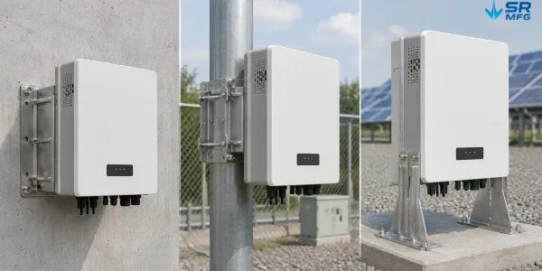
This image compares wall-mounted, pole-mounted, and ground-mounted solar inverter bracket configurations.
Typical application: Multiple 50 kW string inverters installed on concrete platforms at a 5 MW ground-mounted solar farm, with 2-meter spacing between adjacent units to allow maintenance access and cable routing.
Custom Sheet Metal Fabrication
Every bracket starts with your actual project requirements — not with a standard catalog selection.
- Drawing Submission: Send .dwg, .step, or .pdf files. Our engineering team reviews manufacturability and provides DFM feedback within 24 hours.
- Material Thickness: 1.5 mm to 6.0 mm, selected according to load calculations and environmental corrosion classification.
- Hole Layout: CNC punched or drilled according to the inverter backplate dimensions. Slotted-hole designs are available for compatibility with multiple brands.
- Surface Finish: Hot-dip galvanizing with a zinc coating ≥85 μm for C3–C4 environments; Type III anodizing at 25–50 μm for C5-M marine environments; polyester powder coating at 60–80 μm DFT in any specified RAL color for architectural applications.
- Tilt Angle: Manufactured at any specified fixed angle, or continuously adjustable from 0°–90° using curved slots and locking bolts.
- Kit Supply: Brackets can be supplied individually or as complete installation kits with fasteners, isolation washers, and mounting templates, including specified torque requirements.
- Prototype Lead Time: 7–15 working days. Mass Production Lead Time: 15–30 working days, depending on order quantity and surface treatment requirements.
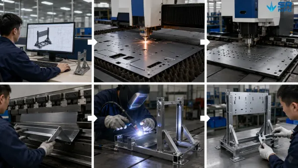
This image shows the main manufacturing stages used to produce custom solar inverter mounting brackets.
Get a Custom Quote
Send us your inverter model, mounting scenario, and project location. Our engineering team will determine the most suitable bracket configuration and provide a detailed quotation within 24 hours.
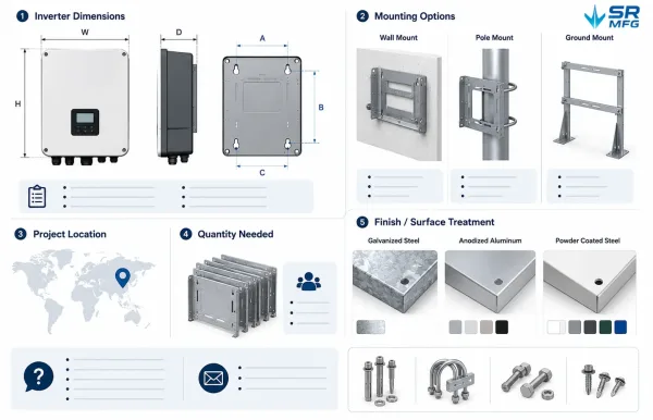
This image shows the project information required to prepare a custom solar inverter mounting bracket quotation.
Information Required:
· Inverter model or dimensional drawing
· Mounting method: wall-mounted / pole-mounted / ground-mounted
· Project location, including corrosion environment classification if known
· Estimated purchase quantity
· Preferred surface treatment
[Send Your Drawings for Custom Pricing]