Custom Automation Machine Base Frame
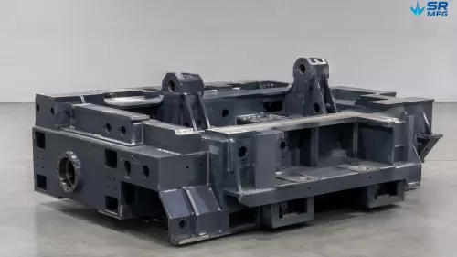
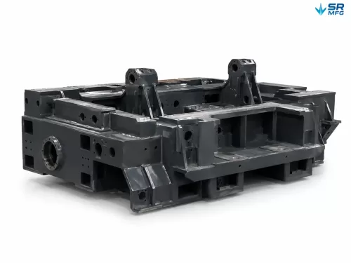
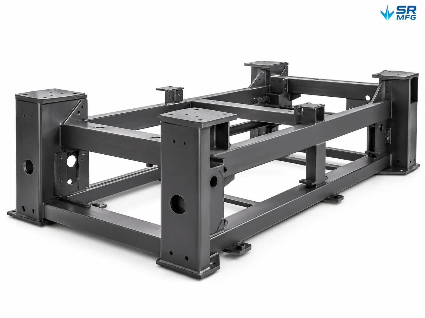
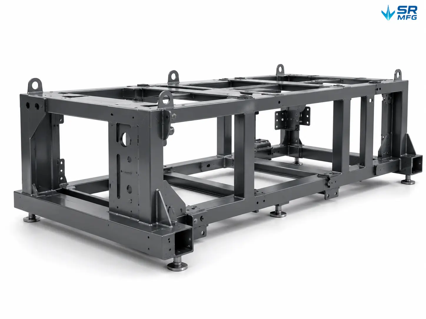
A rigid welded steel base frame designed to support automation equipment, robotic workstations, and custom machinery. Manufactured from square steel tubing and laser-cut sheet metal components, with precision-machined mounting interfaces for accurate assembly.
Core Capabilities:
- Material Options: Carbon steel (Q235B / Q355), stainless steel (304 / 316), aluminum alloy (6061 / 5052)
- One-Stop Fabrication: Laser cutting → CNC bending → welding → stress relief → CNC machining → surface treatment → inspection
- Drawing-Based OEM Fabrication: Send us your CAD files. We review your design, confirm the requirements, provide a quotation, and deliver finished frames ready for installation.
Product Details
| Parameter | Specification |
|---|---|
| Product Name | Custom Automation Machine Base Frame |
| Materials | Carbon steel (Q235B / Q355), stainless steel (304 / 316), aluminum alloy (6061 / 5052) |
| Material Thickness Range | 3 mm – 60 mm, depending on material |
| Maximum Fabrication Size | Up to 12,000 × 2,500 × 2,000 mm (L × W × H) |
| Structure Types | Welded square tube frame, welded plate structure, tube + plate combination, integrated bent frame |
| Welding Processes | MIG/MAG, TIG, laser welding, robotic welding |
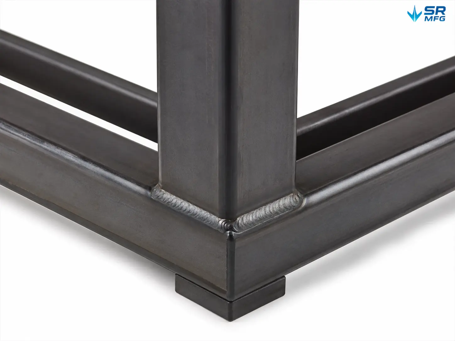
| Welding Quality | Continuous fillet welds at structural joints; weld quality to ISO 5817 Class C, upgradeable to Class B for critical or visible welds |
| Dimensional Tolerance | Welded structures: ISO 13920 Class B/C; machined surfaces: per drawing, with critical features achievable to ±0.01 mm; general features: ISO 2768 m/f |
| Flatness (Datum Pads) | ≤1.0–2.0 mm on machined datum surfaces |
| Stress Relief | Thermal stress relief (oven treatment) or vibratory stress relief |
| Surface Preparation | Sandblasting to Sa 2.5 (ISO 8501) |
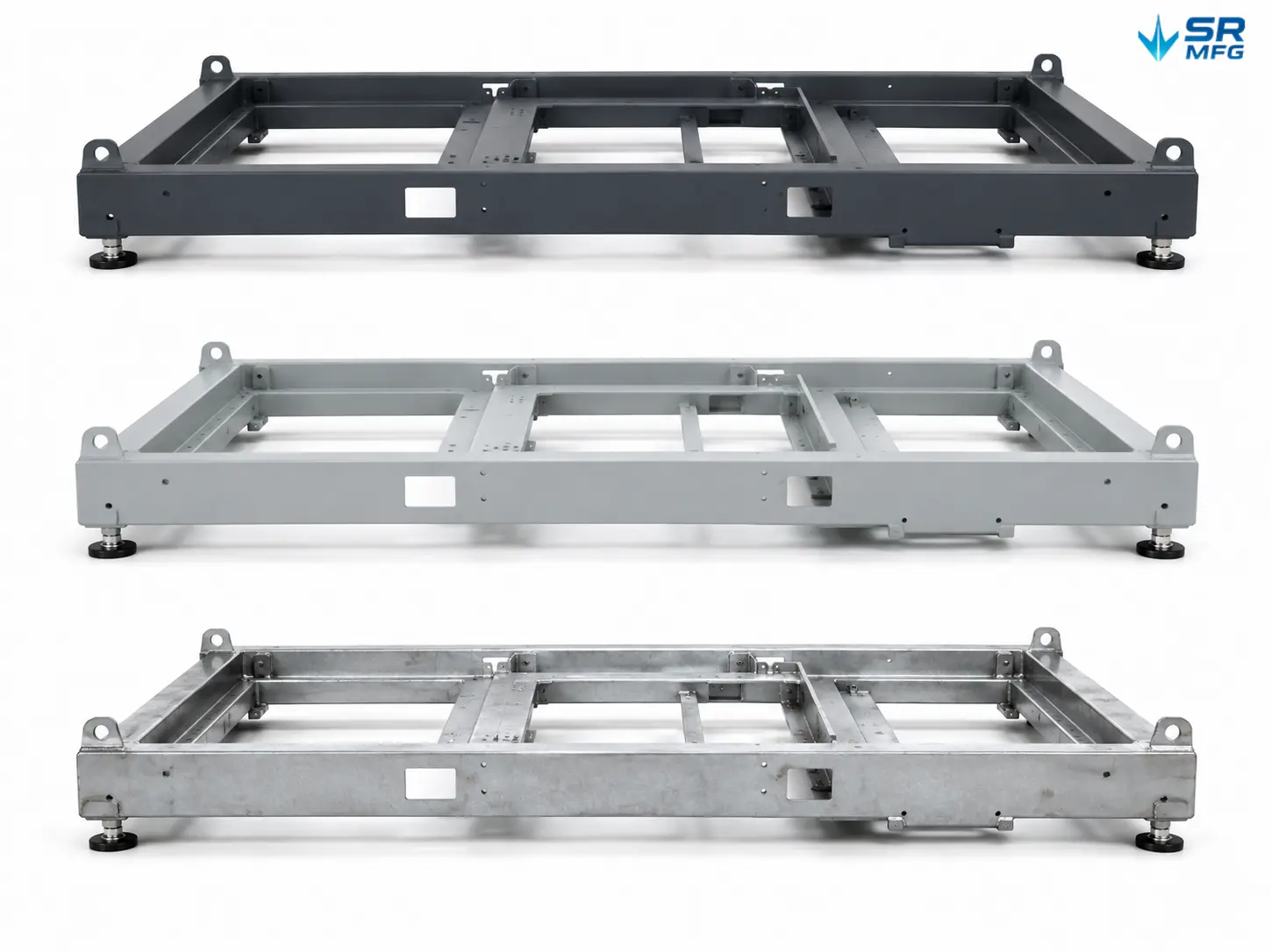
| Surface Treatment Options | Powder coating (70–100 μm DFT), industrial painting (primer + topcoat), hot-dip galvanizing, zinc plating |
| Inspection | 100% visual weld inspection, CMM dimensional verification, DFT coating thickness measurement; NDT (UT/MT) available on request |
| Quality Documentation | Dimensional inspection report, material certificates, welding inspection records, coating test reports, WPS/PQR available on request |
| Accepted Drawing Formats | STEP, IGES, DWG, DXF, PDF, SolidWorks |
| MOQ | Prototype and small-batch orders welcome |
| Typical Lead Time | Prototype: 7–15 working days; mass production: 15–30 working days, depending on complexity and quantity |
| Packing | Reinforced pallets / steel frame packing / anti-rust protection / moisture-barrier packaging |
A Stable Foundation for Your Automation System
An automation machine base frame is the structural foundation of your equipment. It determines whether the machine remains properly aligned, whether individual modules can be positioned accurately, and whether the production line can operate without unexpected downtime. When a frame warps, mounting holes shift, or datum surfaces are not flat, every downstream assembly step becomes more difficult.
We manufacture custom welded steel base frames for non-standard automation equipment, robotic workstations, CNC auxiliary equipment, inspection systems, and production-line modules. Every frame is manufactured to your drawings, machined to your specified tolerances, and finished according to the actual operating environment.
Why Choose Our Machine Base Frames
Rigid Welded Structure
Square steel tubing and laser-cut plate components are assembled using fixture-assisted welding to control distortion. The finished frame maintains its geometry not only at the time of delivery, but also under load and vibration after thousands of hours of operation.
Precision-Machined Mounting Interfaces
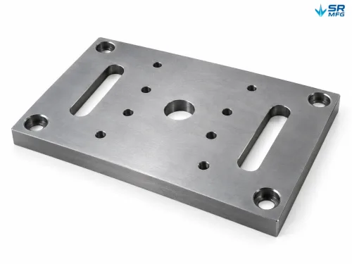
Critical surfaces—including mounting pads, datum surfaces, and hole patterns—are CNC-machined after welding. These are the interfaces where servo drives, sensors, linear modules, and actuators are ultimately installed. Flatness, parallelism, and hole position are controlled according to your assembly requirements.
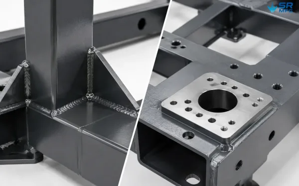
This image shows the welded structural rigidity and precision-machined mounting features of the machine base frame.
One-Stop Production Process
From raw steel to a finished, coated, and inspected frame, our custom sheet metal fabrication process brings cutting, bending, welding, stress relief, machining, coating, and quality inspection together within one manufacturing facility. This eliminates the need to coordinate multiple suppliers and reduces the risk of interface mismatches between different vendors.
Stress Relief for Long-Term Stability
Post-weld heat treatment or vibratory stress relief removes residual internal stresses before machining. This step helps prevent the frame from gradually twisting or losing alignment after months of equipment operation.
Flexible Order Quantities
We support prototypes, trial production, small batches, and volume production. Whether you need one frame for a new automation cell or 50 frames for a production-line expansion, we apply the same manufacturing process and quality standards.
How We Manufacture Your Machine Base Frame
Every frame follows a controlled manufacturing process designed to ensure dimensional accuracy and long-term structural stability.
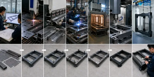
This image shows the main production stages used to manufacture a custom automation machine base frame.
Step 1 — Drawing Review & Engineering Confirmation
We review your 2D or 3D drawings for material selection, structural feasibility, welding sequence, and machining scope. Before production begins, we confirm hole positions, bracket layouts, stiffener requirements, and tolerance callouts.
Step 2 — Material Selection & Incoming Inspection
Steel plates and tubes are sourced according to specification, including Q235B, Q355, SS304, SS316, or aluminum alloys. Material certificates are available upon request. All incoming material is inspected before cutting.
Step 3 — Laser Cutting & CNC Bending
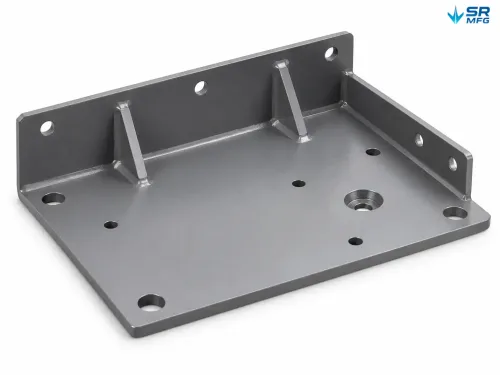
Sheet metal components are laser-cut to achieve clean edges and accurate profiles. Brackets, mounting plates, and stiffeners are CNC-bent to the required angles with consistent dimensional repeatability.
Step 4 — Fixture-Assisted Welding Assembly
Components are assembled using custom fixtures and jigs for fixture-assisted sheet metal welding to maintain geometry during welding. The welding sequence is planned to minimize heat input and control distortion. Continuous fillet welds can be used at structural joints.
Step 5 — Post-Weld Stress Relief
Thermal stress relief using oven treatment or vibratory stress relief is applied to remove residual stresses generated during welding. This is especially important for equipment frames that must maintain alignment over many years of operation.
Step 6 — CNC Machining of Critical Mounting Interfaces
After stress relief, mounting surfaces, datum planes, drilled holes, tapped holes, and slots are CNC-machined. This process is used to achieve flatness of ≤1.0 mm, accurate hole positioning, and the required surface finish.
Step 7 — Surface Treatment
Frames are first sandblasted to Sa 2.5, then finished according to project requirements using powder coating, industrial painting with primer and topcoat, hot-dip galvanizing, or zinc plating. The coating system is selected based on the actual operating environment.
Step 8 — Inspection & Quality Verification
Every frame undergoes 100% visual weld inspection. Critical dimensions are verified using a CMM (Coordinate Measuring Machine). Inspection reports, dimensional records, and material certificates are available upon request.
Step 9 — Export Packing & Delivery
Large frames are packed on reinforced pallets or steel frames with protective wrapping, anti-rust treatment, and moisture-barrier materials. Packaging is designed to protect the product during ocean or air freight.
Where These Machine Base Frames Are Used
Our automation machine base frames are used across a wide range of machinery and industrial equipment applications:
- Non-Standard Automation Equipment — Provides a rigid, precision-machined foundation for custom machinery requiring accurate module integration.
- Robotic Workstations and Automation Cells — Base structures for industrial robots such as KUKA, FANUC, ABB, and Yaskawa, as well as collaborative robot integration tables and fixture positioning platforms.
- CNC Machine Auxiliary Structures — Support frames for peripheral equipment, tool changers, and workpiece handling systems.
- Inspection and Metrology Equipment — Stable base structures for coordinate measuring machines, vision inspection systems, and laser scanning equipment.
- Packaging and Sorting Line Structures — Support frames for conveyor modules, sorting mechanisms, and product handling stations.
- Modular Production-Line Frames — Reconfigurable base structures for assembly-line equipment, test fixtures, and process stations.
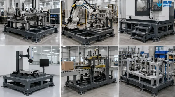
This image shows several industrial applications where machine base frames are used as equipment support structures.
Customization Options & Design Recommendations
Every project starts with your drawings. Below are the areas we can customize, along with several recommendations for achieving better manufacturing results.
Customization Options:
- Overall dimensions (L × W × H)
- Hole patterns and threaded hole positions
- Mounting bracket locations for sensors, panels, actuators, and enclosures
- Stiffener layouts designed according to load and vibration requirements
- Machining scope and tolerance levels
- Surface treatment type and color
- Packing method customized for your shipping route
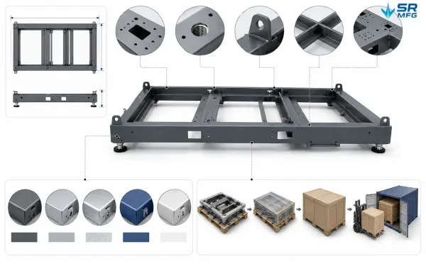
This image shows the main customization options available for a machine base frame project.
Accepted Drawing Formats: STEP, IGES, DWG, DXF, PDF, SolidWorks
Design Recommendations for Better Results:
· Separate critical and non-critical tolerances. Tighter tolerances on mounting interfaces improve assembly accuracy, while looser tolerances on non-critical surfaces can reduce machining costs.
· Consider stiffener placement early. Proper stiffener positioning can significantly improve frame rigidity without adding unnecessary weight.
· Specify the operating environment. Indoor workshops, outdoor installations, chemically exposed environments, and cleanrooms each require different surface treatment strategies.
How to Get Started:
- Send us your 2D or 3D drawings together with the material, quantity, and target delivery date.
- Our engineering team will review the project and confirm feasibility within 24 hours.
- You will receive a quotation including pricing, lead time, and packing details.
- Once the order is confirmed, we begin production and provide full quality documentation.
FAQs
Ready to Start Your Project?
Send us your drawings or project requirements. Our engineering team will review the feasibility of your project and provide a quotation within 24 hours.
We are also happy to sign an NDA before reviewing your drawings.