
H68/H70 Brass
Cold Formability
Deep-Draw Performance
Corrosion Resistance
H68/H70 Brass: Basic Overview
Both H68 and H70 are copper-zinc brasses, commonly referred to as standard brass. The main difference between them is copper content: H68 contains 67% to 70% copper, while H70 contains about 68.5% to 71.5%.
Even a small difference in copper content can lead to noticeable differences in performance, which is why this point deserves attention.
Both grades are single-phase alpha brasses. At room temperature, they have a single crystal structure and offer excellent ductility and forming toughness. That is one of the main reasons they are so widely used in sheet metal fabrication.
In some projects, H68 and H70 are considered side by side because their copper content is relatively close, and in many applications they can be used interchangeably.
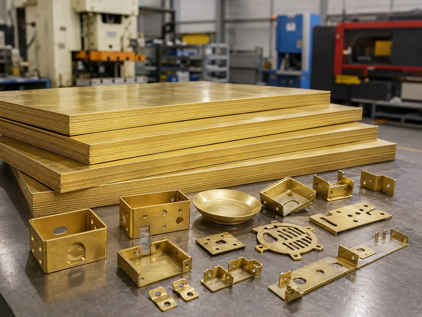
Quick Identification Guide for H68/H70 Brass
| Grade | Material Category | Common Supply Forms | Common Application Areas |
|---|---|---|---|
| H68 | Single-phase alpha brass (copper-zinc alloy) | Sheet, strip, tube, bar | Complex deep-drawn parts, housings, tubes, radiators, cartridge cases, terminals |
| H70 | Single-phase alpha brass (copper-zinc alloy) | Sheet, strip, tube, bar | Sheet metal stampings, conductive parts, decorative parts, hinges, connectors |
What Is the Difference Between H68 and H70 Brass?
The core difference between H68 and H70 has already been mentioned in the overview above. The sections below explain the specific differences in more detail.
H68 vs. H70 Brass Comparison
| Comparison Item | H68 | H70 | Material Selection Note |
|---|---|---|---|
| Copper content | 67%–70% | 68.5%–71.5% | Difference is about 1%–1.5% |
| Ductility / elongation | Excellent, 35%–45% | Good, 30%–35% | H68 is preferred for complex deep-drawn parts |
| Deep drawing capability | Excellent, drawing ratio up to 8:1 | Good, suitable for standard deep drawing | Choose H68 for extreme deep-drawing requirements |
| Tensile strength, annealed | ≥290 MPa | 370–470 MPa | Select based on strength requirements |
| Tensile strength, hard temper | Up to 660 MPa | 470–560 MPa | High-strength tempers are easier to achieve with H68 |
| Electrical conductivity | About 27% IACS | 38%–44% IACS | Choose H70 first when conductivity matters |
| Thermal conductivity | 116–121 W/(m·K) | About 120 W/(m·K) | The two are close |
| Weldability | Good | Better | Both are suitable for standard welding applications |
| Typical part types | Complex formed parts, thin-wall deep-drawn parts, precision housings | Conductive parts, decorative sheet metal parts, standard stamped parts | Choose based on part complexity and functional requirements |
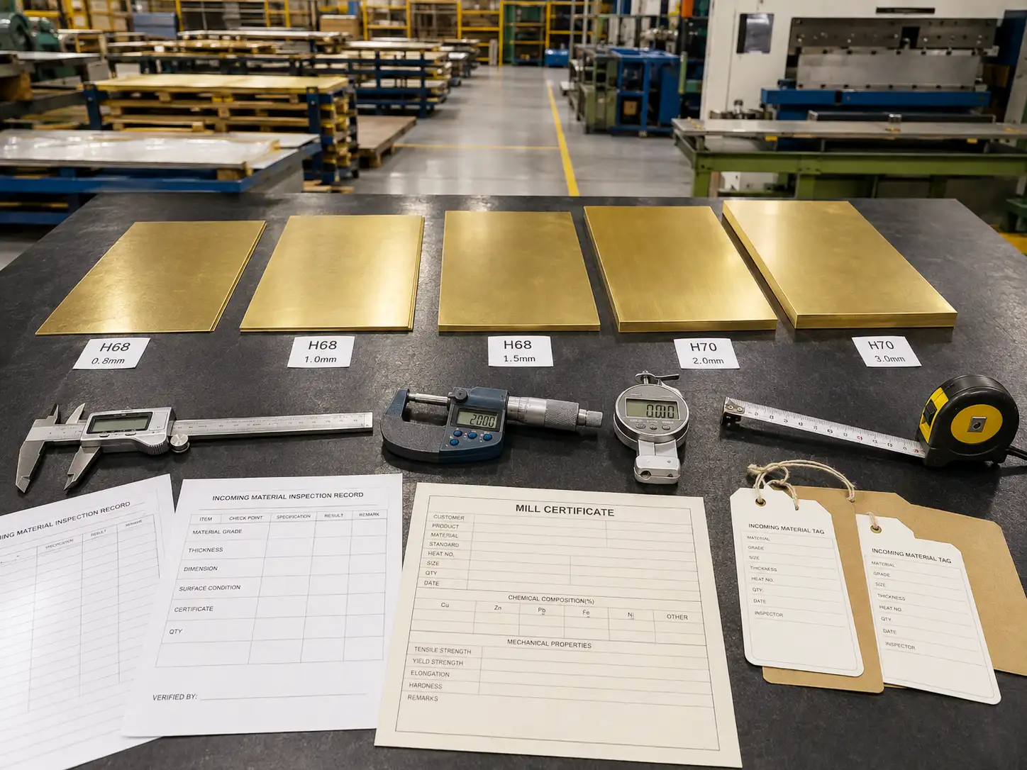
Chemical Composition of H68/H70 Brass
| Element | H68 (%) | H70 (%) | Notes |
|---|---|---|---|
| Copper (Cu) | 67.0–70.0 | 68.5–71.5 | Primary element |
| Zinc (Zn) | Balance, approx. 30–33 | Balance, approx. 28.5–31.5 | Alloying element |
| Lead (Pb) | ≤ 0.03 | ≤ 0.05 | Impurity control |
| Iron (Fe) | ≤ 0.10 | ≤ 0.10 | Impurity control |
| Nickel (Ni) | ≤ 0.05 | ≤ 0.05 | Impurity control |
| Tin (Sn) | ≤ 0.05 | ≤ 0.05 | Impurity control |
| Total other impurities | ≤ 0.3 | ≤ 0.3 |
Physical Properties of H68/H70 Brass
| Temper | Thickness Range | Tensile Strength | Elongation | Hardness |
|---|---|---|---|---|
| O60, annealed soft | 0.3 to 10 mm | ≥290 MPa | ≥40% | HV ≤ 90 |
| H01, quarter-hard | 0.3 to 10 mm | 325 to 410 MPa | ≥35% | HV 85 to 115 |
| H02, half-hard | 0.3 to 10 mm | 355 to 440 MPa | ≥25% | HV 100 to 130 |
| H04, hard | 0.3 to 10 mm | 410 to 540 MPa | ≥10% | HV 120 to 160 |
| H06, extra hard | 0.3 to 10 mm | 520 to 620 MPa | ≥3% | HV 150 to 190 |
| H08, spring temper | 0.3 to 10 mm | ≥570 MPa | To be confirmed by agreement | HV ≥ 180 |
| M20, hot-rolled | 4 to 60 mm | ≥290 MPa | ≥40% | To be confirmed by agreement |
Supply Forms and Tempers of H68/H70 Brass
| Product Form | Common Tempers | What to Focus On |
|---|---|---|
| Sheet | O60, H01, H02, H04 | Housings, covers, deep-drawn parts, bent parts |
| Strip | O60, H01, H02, H04, H06, H08 | Terminals, spring contacts, progressive stamping parts |
| Bar | H02, H04, and others | Secondary machining, connectors, fasteners |
| Tube | Annealed, hard temper, and others | Tubes, heat-transfer-related parts, assembly components |
| Wire / flat wire | O60, H00, H02, H04, and others | Cold heading, fasteners, small conductive parts |
What Sheet Metal Fabrication Processes Are H68/H70 Brass Suitable For?
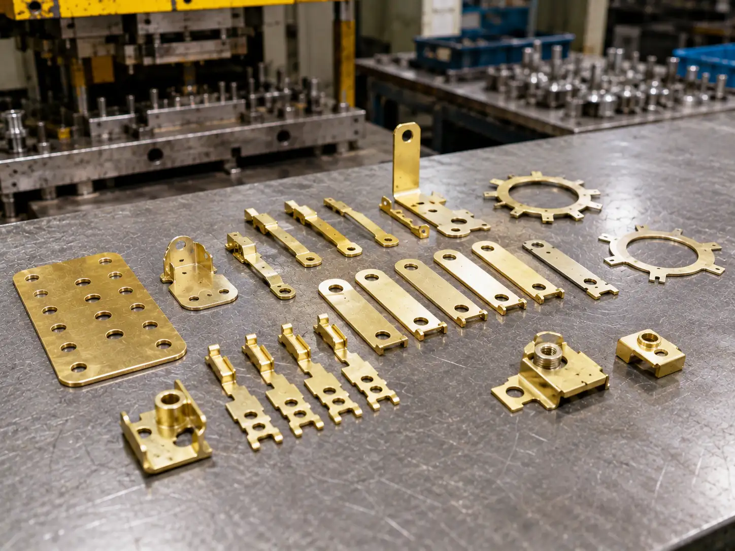
Stamping / Blanking
Both H68 and H70 are very well suited to standard stamping, punching, and blanking processes. Within the usual sheet metal thickness range of 0.3 mm to 3.0 mm, cut-edge quality is generally stable. Both grades are also commonly used for complex cold-stamped parts and deep-drawn parts.
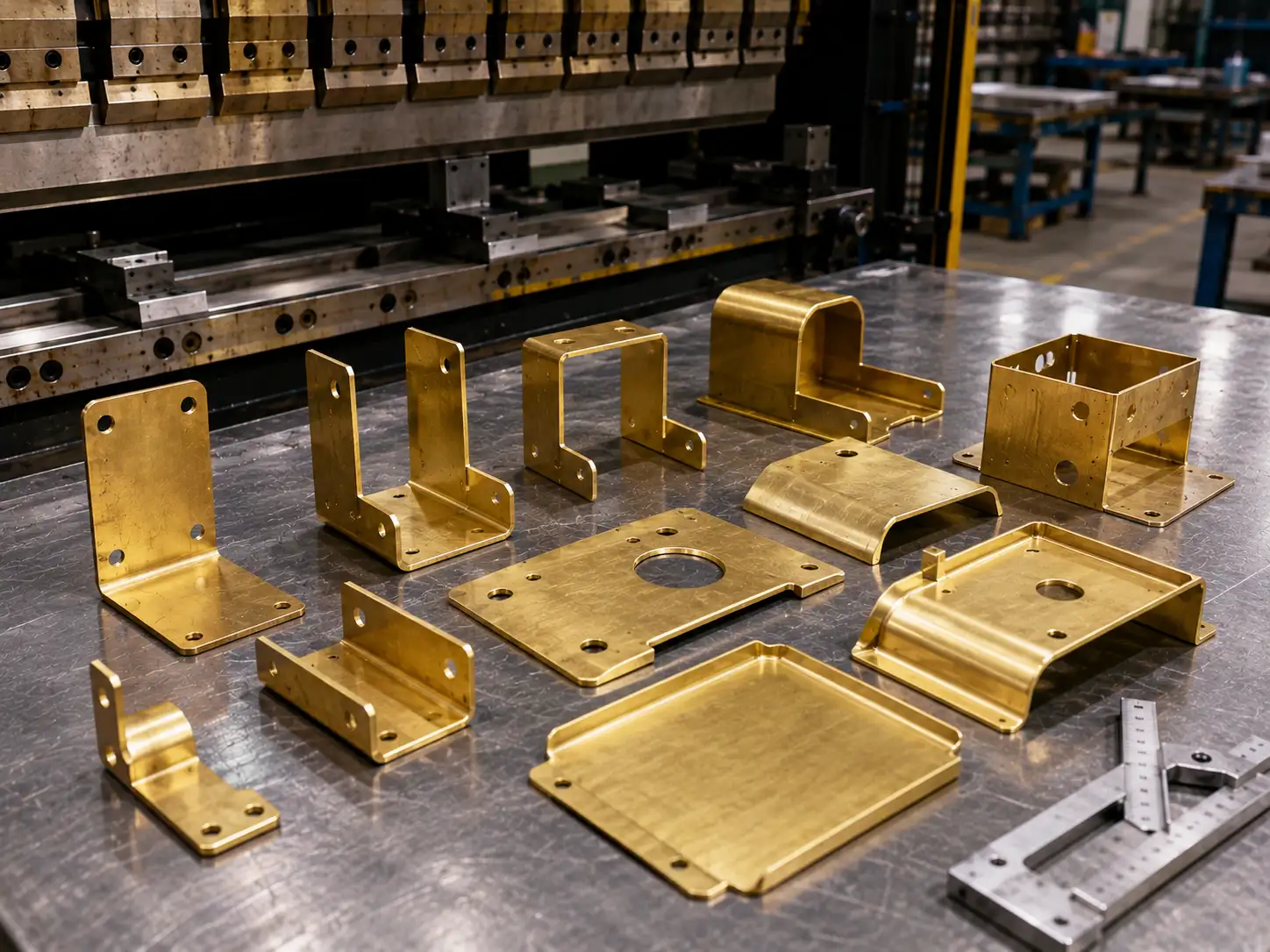
Bending and Forming
The bending performance of H68 and H70 depends mainly on the temper selected. In annealed and half-hard tempers, both grades can achieve relatively small bend radii, typically around one material thickness. For hard tempers, a larger bend radius of about 1.5 to 2 times the material thickness is generally recommended to reduce the risk of cracking on the outer surface.
Deep Drawing and Complex Cold Forming
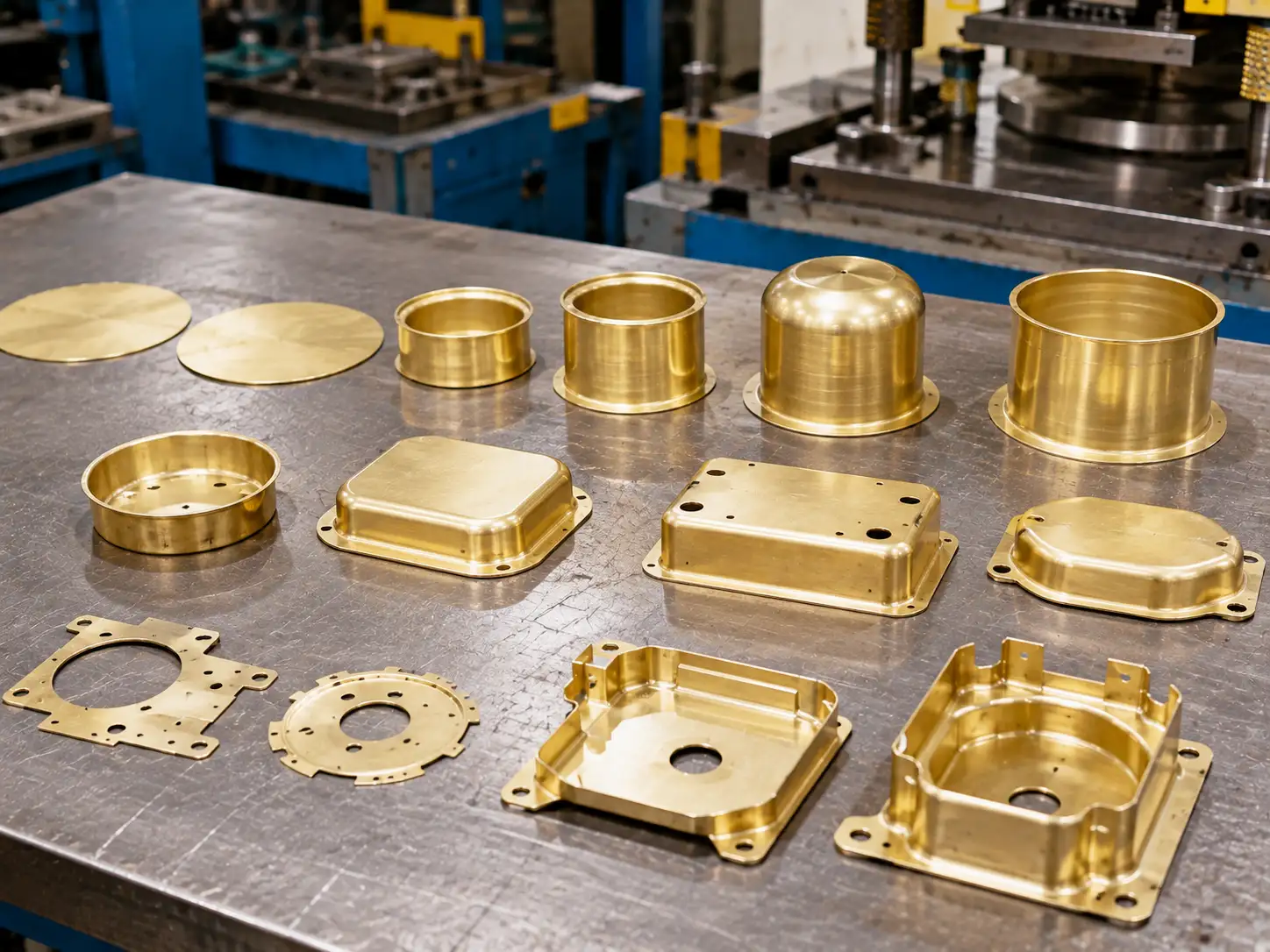
Deep drawing and complex cold forming are among the strongest process advantages of H68 and H70. Both grades offer excellent ductility within the brass family and are especially well suited to housings, covers, and thin-wall deep-drawn parts. H70, with its higher elongation, tends to perform more consistently in parts with large drawing ratios. H68 is often preferred for deep-drawn parts that still need to retain a certain level of strength after forming.
Machining and Secondary Operations
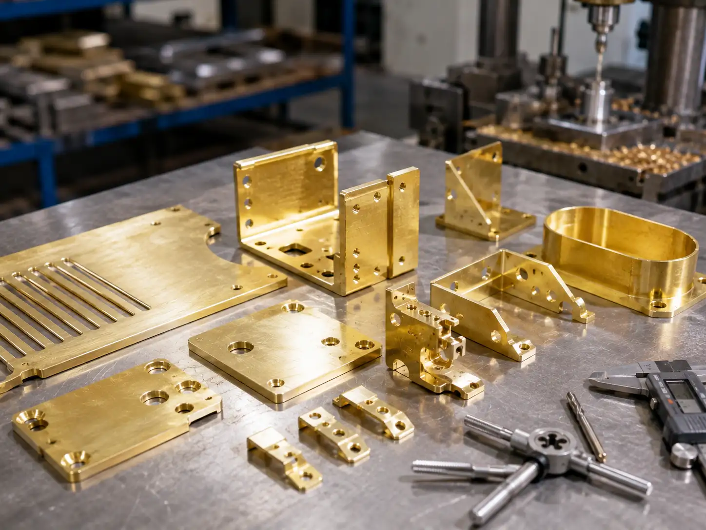
Some stamped parts also require secondary operations such as polishing, tapping, deburring, or drilling after forming. H68 and H70 both offer good machinability and can deliver stable machining quality under standard processing conditions.
Process Compatibility of H68/H70 Brass
| Process Type | Suitability | Key Considerations | Typical Part Examples |
|---|---|---|---|
| Stamping and blanking | Suitable | Die clearance, burr control, hole-edge quality | Washers, terminals, covers, contact strips |
| Bending and forming | Suitable | Temper, bend radius, springback | Brackets, clips, enclosure frames |
| Deep drawing and complex cold forming | H70 has a stronger advantage, though H68 is also widely used | Drawing ratio, corner radius, lubrication, number of forming steps | Housings, covers, tubes, bellows |
| Machining and secondary operations | Suitable as a supporting process route | Tapping, edge trimming, drilling, tolerance transition | Post-stamping machined parts, assembly connectors |
| Welding and brazing | High compatibility with brazing | Joint cleanliness, heat effects, surface protection | Tube assemblies, contact connection parts |
Surface Finishing and Appearance Considerations for H68/H70 Brass
Common Surface Treatments and Typical Applications for H68/H70 Brass
| Surface Treatment | Main Purpose | Suitable Part Types | Items to Confirm in Advance |
|---|---|---|---|
| Nickel plating | Corrosion resistance and wear resistance | Fasteners, structural parts | Coating thickness, sealing requirements |
| Tin plating | Improved solderability and corrosion resistance | Conductive parts, terminals | Post-plating storage conditions, solderability testing |
| Silver plating | Improved conductivity and appearance | High-frequency connectors, contacts | Coating thickness, anti-tarnish treatment |
| Gold plating | Conductivity and reliability | High-end connectors, precision contacts | Cost considerations, coating thickness |
| Polishing | High-gloss appearance | Decorative parts, appliance panels | Gloss level, uniformity |
| Brushed finish | Textured surface appearance | Electronic housings, panels | Grain direction, texture fineness |
| Passivation / anti-oxidation treatment | Short-term tarnish protection | Stock parts, semi-finished parts | Protection period, packaging method |
| Protective oil coating | Medium-term corrosion protection | Parts awaiting assembly | Whether it affects subsequent assembly or welding |
Application Scenarios and Material Selection Priorities for H68/H70 Brass
| Part Type | Typical Requirements | Material Direction to Prioritize | Design Note |
|---|---|---|---|
| Terminals, contact clips | Conductivity, stamping performance, localized spring properties | H70 | Confirm strip temper and plating requirements first |
| Decorative covers, nameplates | Appearance, flatness, surface consistency | H68 or H70 | Confirm the incoming sheet surface grade and protective film first |
| Thin-wall stamped parts | High-volume stamping, hole-edge quality, assembly fit | H68 | Die clearance and burr direction should be confirmed in advance |
| Deep-drawn housings | Deep drawing, smooth corner transitions, stable wall thickness | H70 | It is best to validate the drawing window with samples first |
| Tubes, bellows | Formability, joining method, corrosion resistance | H70 | Pay close attention to the joining method and heat effects |
| Conductive parts with appearance requirements | Formability, appearance, conductivity | H70 | Lock in conductivity, plating specification, and appearance standard together |
What Information Should Be Confirmed Before Purchasing H68/H70 Brass Parts?
H68/H70 Brass RFQ Checklist
| Information Category | Required / Recommended | Example | Impact on Quotation or Evaluation |
|---|---|---|---|
| Material grade | Required | H68 or H70 | Different grades vary in price and availability |
| Supply temper | Required | Annealed, half-hard, hard, or supplier-recommended | Affects raw material sourcing and fabrication method |
| Incoming material size | Recommended | Sheet 1000 × 2000 mm, strip width 300 mm | Affects material utilization and nesting layout |
| Finished part dimensions | Required | 200 × 150 × 5 mm | Determines material consumption and processing time |
| Drawing revision | Required | REV.A or latest revision | Ensures the technical requirements are aligned |
| Dimensional tolerance requirements | Recommended | General dimensions ±0.1 mm, critical dimensions ±0.05 mm | Affects processing difficulty and inspection method |
| Quantity / batch volume | Required | First batch 500 pcs, monthly demand 2000 pcs | Affects tooling allocation and unit price |
| Surface finish requirements | Required | Nickel plating 3–5 μm, or polishing to Ra 0.8 | Usually outsourced, so it affects cost and lead time |
| Appearance standard | Recommended | No scratches, no press marks, uniform color | A clear standard or approved sample should be provided |
| Inspection requirements | Recommended | Material certificate, 5% dimensional sampling | Affects quality-control cost |
| Service environment | Recommended | Indoor dry environment, or outdoor humid environment | Affects material choice and surface treatment |
| Lead time requirement | Required | Samples in 2 weeks, mass production in 4 weeks | Affects production scheduling |
