
EV Battery Pack Upper Cover
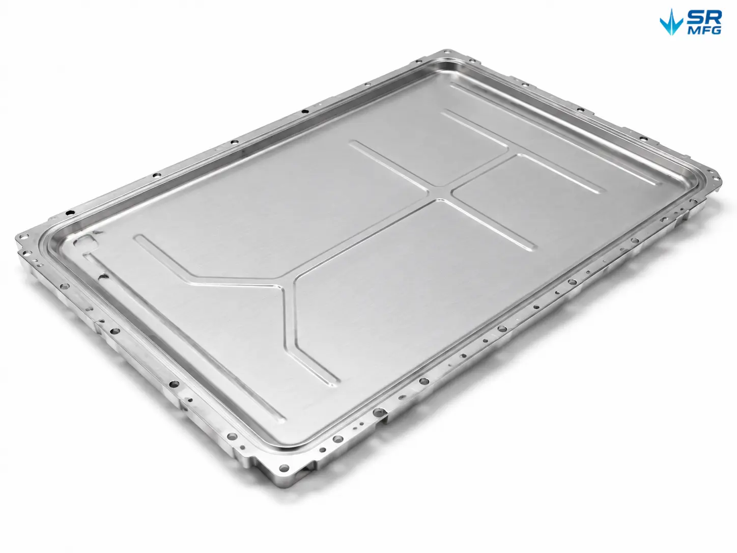
Custom-manufactured EV battery pack upper covers built to your drawings. We provide deep drawing, stamping, and welding services for aluminum and steel enclosure lids used in automotive battery systems — from prototyping through volume production.
- Material Options: Aluminum 3003 / 5052 / 6061, stainless steel, high-strength steel
- Process Capabilities: Deep drawing, stamping, laser cutting, TIG/MIG/laser welding
- Sealing Performance: IP65–IP67 rated, verified by air-tightness testing
- Certifications: Production facility certified to IATF 16949 and ISO 9001 → Submit your drawings for a free DFM review and a custom quote.
Product Details
| Specification | Parameter |
|---|---|
| Product Type | Battery pack upper cover / enclosure lid |
| Compatible Vehicles | Battery Electric (BEV), Plug-in Hybrid (PHEV), Hybrid (HEV), commercial EVs, energy storage systems |
| Material Options | Aluminum 3003 / 5052 / 6061; Stainless Steel 304 / 316; Low-Carbon Steel DC01 / SPCC |
| Material Thickness | 0.8–3.0 mm (aluminum); 0.8–2.0 mm (steel) |
| Maximum Part Size | 1500 mm × 1000 mm |
| Maximum Draw Depth | 150 mm |
| Dimensional Tolerance | Standard ±0.1 mm; Precision ±0.05 mm |
| Flatness | Standard ≤0.5 mm/m; tighter tolerance available upon request |
| Surface Roughness | Ra 1.6–3.2 μm (post-machining); finer finish available upon request |
| Welding Standard | ISO 5817 Class B (visual); leak-tested welds |
| Sealing Performance | IP65 / IP67; pressure-decay air-tightness test |
| Sealing Method | Seal groove + EPDM/silicone gasket; adhesive bonding; combination seal |
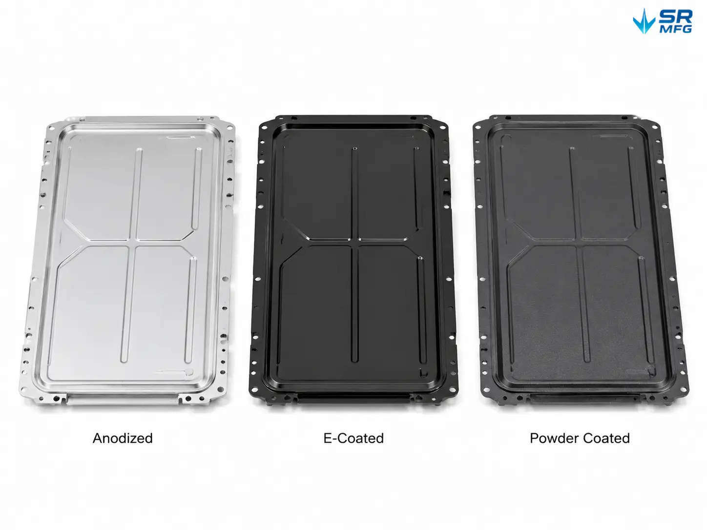
| Surface Treatment | Anodizing (Type II/III), e-coating, powder coating, passivation, chromate conversion |
| Coating Thickness Verification | Per ASTM B487 / ISO 2064 |
| Inspection Methods | CMM, gauge inspection, air-tightness testing, weld visual inspection |
| Quality System | IATF 16949, ISO 9001 |
| Prototype Lead Time | 7–15 business days |
| Production Lead Time | 15–30 business days |
| Minimum Order Quantity | Project-based; no strict MOQ enforced |
| Drawing Formats | STEP, IGES, DWG, DXF, PDF |
| Packaging | Custom foam-lined packaging; palletized for bulk shipments |
What Is an EV Battery Pack Upper Cover?
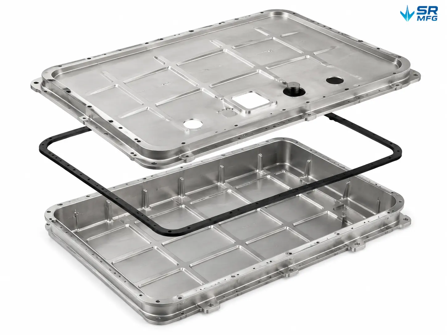
The upper cover is the top sealing panel of an EV battery enclosure. It mates with the EV battery pack lower tray to form a sealed cavity that protects the battery modules, BMS boards, and thermal management components from moisture, dust, vibration, and impact.
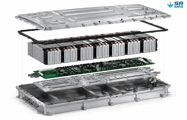
Shows the layered structure of an EV battery pack from top to bottom — upper cover, EPDM gasket, battery cell modules, BMS board, thermal management plates, and lower tray — illustrating where the upper cover sits within the complete assembly.
In a typical battery pack assembly, the upper cover forms the primary sealing interface. Its geometry must accommodate gasket grooves, mounting holes, harness pass-throughs, sensor ports, and pressure-relief vents — all while maintaining strict flatness tolerances to ensure reliable gasket compression.
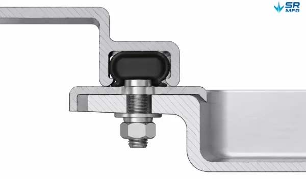
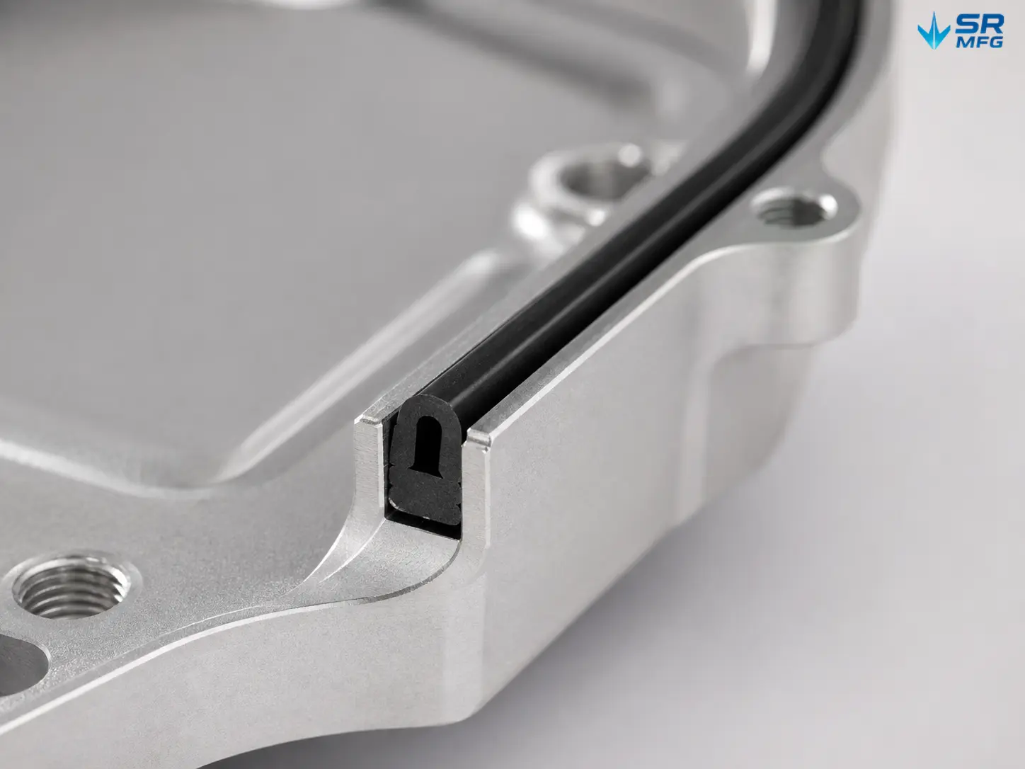
Cross-section cutaway of the sealing interface between the upper cover and lower tray, showing the U-shaped seal groove, compressed EPDM gasket, flange contact surfaces, and bolt fastening — the mechanism behind IP65/IP67 sealing performance.
We manufacture these covers entirely to customer drawings. Whether your design calls for a one-piece deep-drawn aluminum lid with stiffening ribs or a laser-cut steel panel with precision-welded flanges, we can build the tooling, execute the process, and deliver parts that fit the lower tray perfectly on the first assembly.
Material Options
The right alloy depends on your battery pack architecture, weight budget, and corrosive environment. Here is a comparison of the most common options:
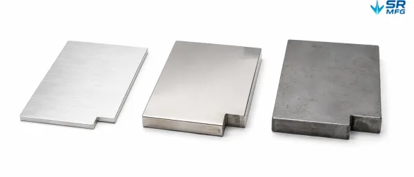
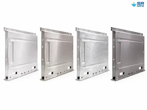
Three rectangular panel samples representing the most common battery cover materials — brushed anodized aluminum on the left, polished stainless steel in the center, and untreated low-carbon steel on the right — displaying distinct surface textures and edge thicknesses.
| Material | Key Characteristics | Typical Applications |
|---|---|---|
| Aluminum 3003 | Good formability, moderate strength, excellent corrosion resistance | Standard pack covers requiring deep drawing |
| 5052 aluminum | Higher strength than 3003, good weldability, marine-grade corrosion resistance | Covers exposed to road salt or high-humidity environments |
| Aluminum 6061 | High strength, heat-treatable, good machinability | Structural covers requiring added rigidity or secondary machining |
| Stainless Steel 304 | Excellent corrosion resistance, heavier weight | Heavy-duty or commercial EV applications where weight is less critical |
| Stainless Steel 316 | Superior chemical and salt-spray resistance | Coastal or extreme-environment deployments |
| Low-Carbon Steel (DC01 / SPCC) | Low cost, easy to form, requires surface treatment | Cost-sensitive projects with full corrosion protection applied |
If your drawings specify a particular temper (e.g., 5052-H32, 6061-T6), we procure material to that specification and can supply mill certificates upon request.
Manufacturing Process
We manufacture EV battery covers through a multi-stage process optimized for dimensional accuracy and sealing reliability.
- DFM Review — Before any tooling is committed, our engineering team reviews your drawings for manufacturability. We flag potential issues — excessive draw ratios, insufficient radii, overly tight tolerance zones — and suggest improvements that reduce cost without compromising function.
- Tooling — Once the design is approved, we build the deep-draw dies, trimming tools, and welding fixtures. For prototypes, we use soft tooling or CNC-machined inserts to shorten lead times.
- Deep drawing and metal stamping — Aluminum or steel blanks are formed into the cover geometry through multi-stage deep drawing. We control the draw ratio, punch speed, and blank-holder pressure to minimize thinning, wrinkling, and springback.
- Laser Cutting & Trimming — After forming, excess material is removed by laser or CNC punching. Bolt-hole positions, sensor ports, and harness grommet openings are held to ±0.1 mm positional accuracy.
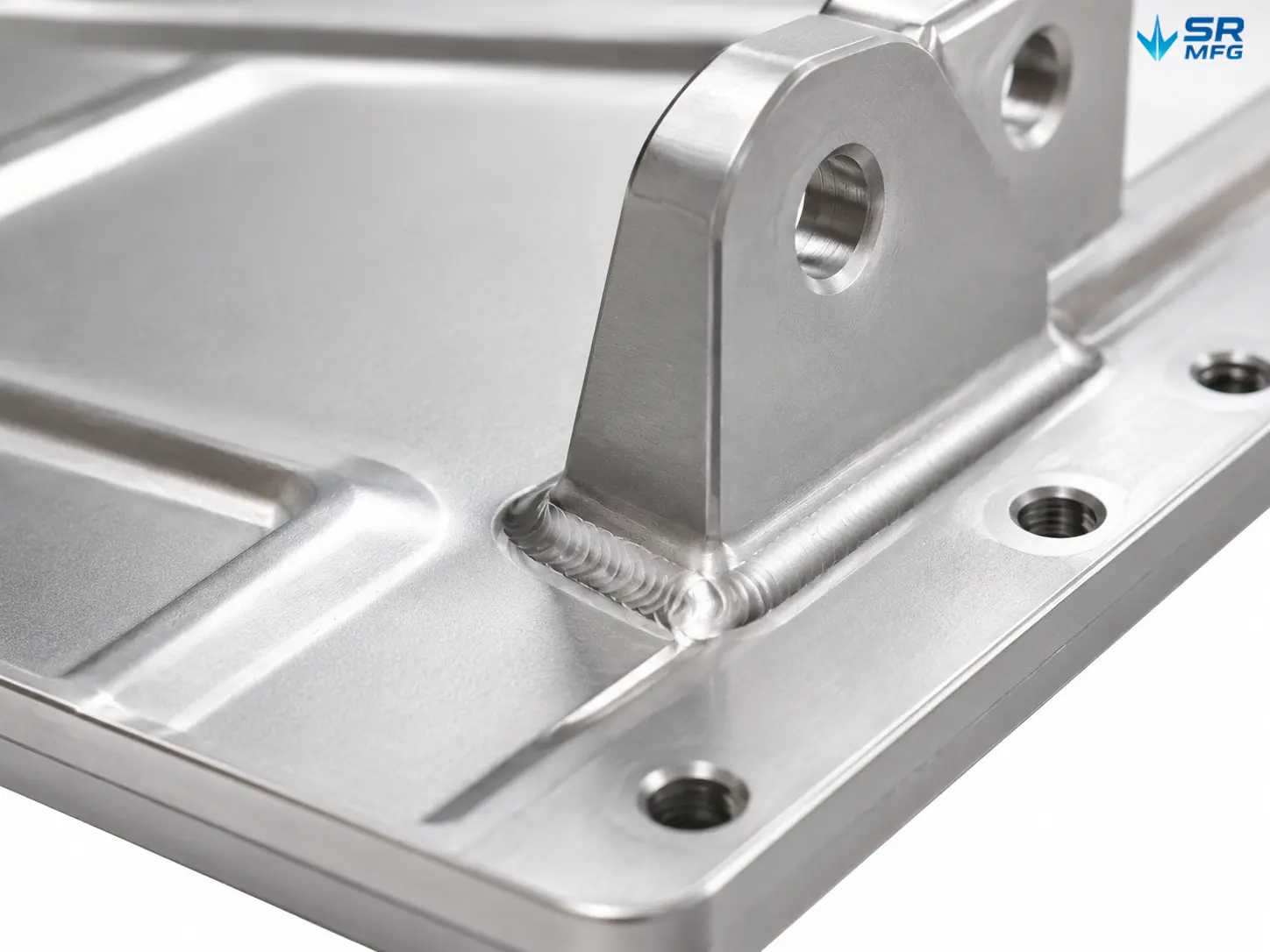
- Welding & Assembly — Flanges, brackets, and reinforcement plates are joined by TIG, MIG, laser, or spot welding depending on the material and joint requirements. All welds are inspected for porosity, undercut, and penetration.
- Surface Treatment — Covers are finished to your specification: anodizing for aluminum, e-coating or powder coating for steel, passivation for stainless steel. Each treatment is verified for coating thickness and adhesion.
- Inspection & Packaging — Every batch undergoes dimensional inspection (CMM or gauge measurement), air-tightness testing (for IP-rated products), weld visual inspection, and surface quality checks. Parts are packaged in custom foam-lined containers to prevent shipping damage.
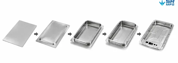
Five progressive stages of the deep drawing process — from a flat aluminum blank to a fully formed upper cover with sidewalls, flanges, and stiffening ribs — showing how the part takes shape through sequential die operations.
Design & Structural Features
A battery pack upper cover is far more than a flat lid. Its structural design directly affects sealing performance, vibration resistance, and assembly efficiency. Here are the key features we manufacture and control:
- Seal Groove: A precision-formed channel along the perimeter that seats the EPDM or silicone gasket. Groove depth and width are controlled to ±0.1 mm, ensuring uniform compression across the entire sealing surface.
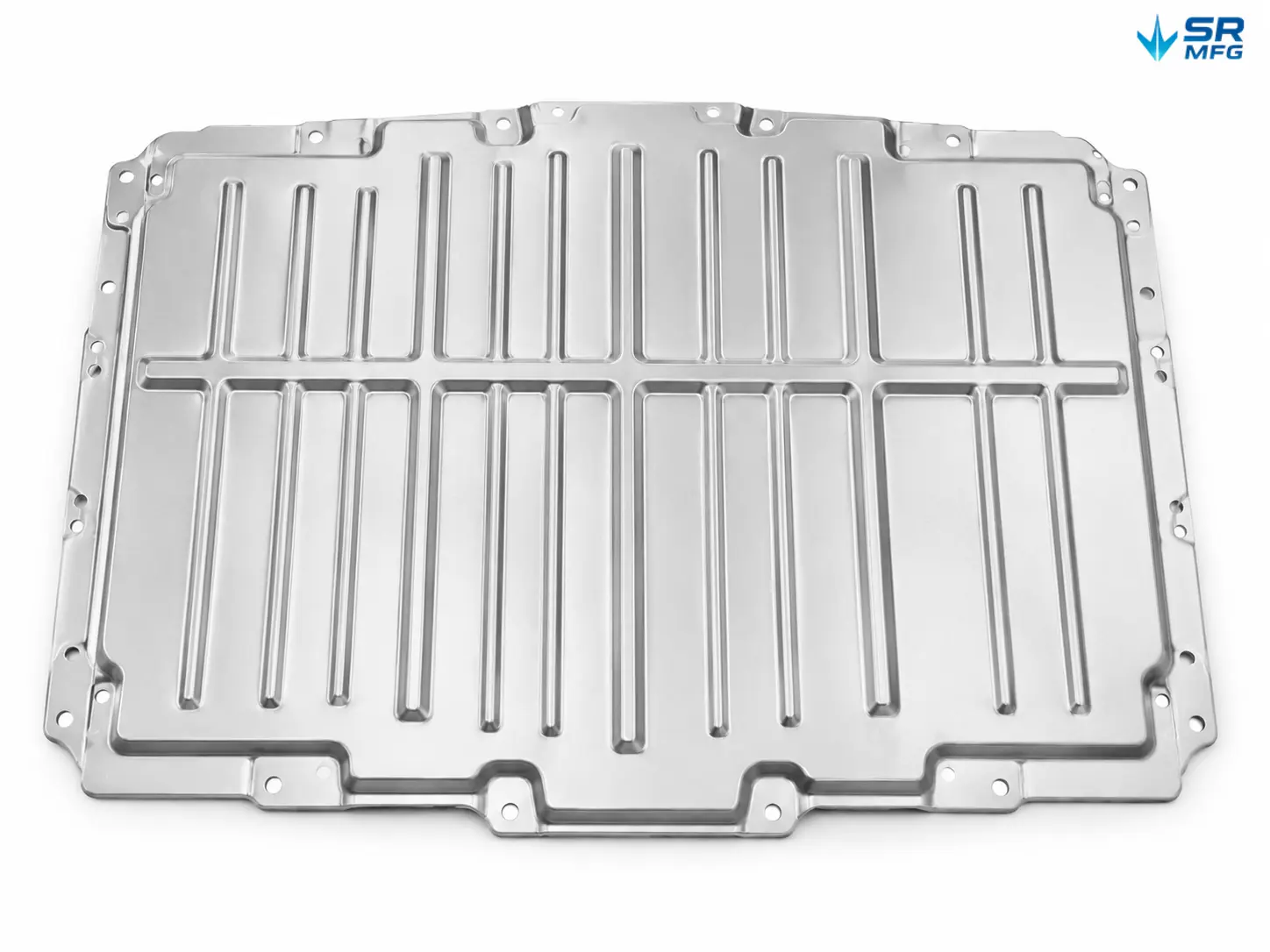
- Stiffening Ribs: Ribs formed through deep drawing or stamping that increase panel rigidity without adding weight. Rib height, spacing, and radii are optimized during the DFM stage to balance strength and formability.
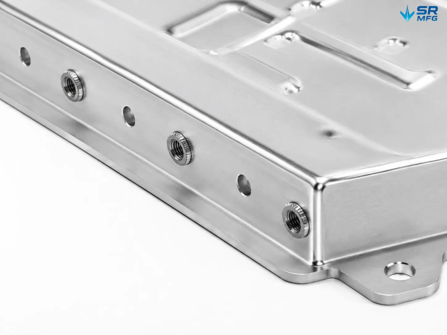
- Mounting Hole Accuracy: Bolt holes used to fasten the tray to the cover are positioned to ±0.1 mm. We can embed press-fit PEM nuts or weld studs during the assembly process.
- Flanges: Bent or drawn lips that add rigidity and create the mating surface with the lower tray. Flange height and angle are held strictly to drawing tolerances.
- Radius Control: Internal and external radii at drawn corners are tightly controlled to prevent cracking during forming and to maintain uniform wall thickness.
- Pass-Through Openings: Cutouts for wiring harnesses, coolant lines, pressure-relief valves, and temperature sensors can be laser-cut or punched during forming — in most cases without requiring secondary operations.
Surface Treatment Options
Surface treatment affects corrosion lifespan, electrical insulation, coating adhesion, and appearance. The right choice depends on your operating environment and pack-level design requirements.
| Treatment | Characteristics | Typical Applications |
|---|---|---|
| Anodizing (Type II) | Decorative + moderate corrosion protection; 5–15 µm film | Standard pack covers requiring appearance and basic protection |
| Anodizing (Type III) | Hard-anodized film; 25–50 µm film; high wear resistance | Covers exposed to abrasion or requiring dielectric strength |
| E-Coating | Uniform coverage over complex geometries; good corrosion protection | Steel covers with complex shapes; automotive-grade finish |
| Powder Coating | Thick, durable finish; wide color selection; good impact resistance | Steel or aluminum covers requiring color matching or heavy-duty protection |
| Passivation | Removes free iron from stainless steel surfaces; enhances corrosion resistance | Stainless steel covers in chemical or saltwater environments |
| Chromate Conversion | Thin protective film; maintains electrical conductivity | Aluminum covers requiring grounding or EMI shielding |
If your battery pack design calls for dielectric testing after coating, we can coordinate insulation resistance verification during the finishing process.
Quality Assurance
Battery enclosure components demand consistent quality. Here is how we control it:
- Incoming Inspection: Alloy composition verification, thickness measurement, surface defect screening.
- In-Process Control: Draw-depth monitoring, welding parameter logging, dimensional spot checks at forming and trimming stations.
- Final Inspection: CMM or gauge-based dimensional audit, air-tightness testing (pressure-decay method) for IP-rated covers, weld visual inspection per ISO 5817 Class B, and surface coating thickness measurement.
- Documentation: Inspection reports, material certificates, and process records are available per batch. PPAP documentation can be provided for automotive programs.
Why Work With Us
- DFM Feedback Before Tooling Commitment: We review every drawing for manufacturability and cost optimization before committing to tooling. This reduces revision cycles and avoids costly rework.
- Seamless Prototype-to-Production Transition: The same team that manages your prototype tooling also manages your production run. No handoff gaps, no lost knowledge.
- Automotive Sheet Metal Fabrication Experience: Our facility operates under IATF 16949 and ISO 9001. We understand PPAP requirements, control plan specifications, and the documentation expectations of EV OEMs and Tier 1 integrators.
- Enclosure Assembly Bundling: We can supply the upper cover, lower tray, gaskets, and mounting hardware as a matched kit — reducing your supplier count and ensuring dimensional compatibility across the entire enclosure.
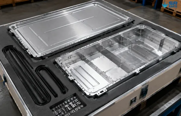
A complete matched battery enclosure kit arranged in a custom foam-lined container — silver aluminum upper cover, lower tray, black EPDM gasket strips, and stainless steel mounting hardware — showing the bundled supply capability in an orderly shipping-ready layout.
FAQs
Ready to Start Your Project?
Every EV battery cover we manufacture begins with your drawing. Send us your STEP, IGES, DWG, or PDF file — our engineering team will perform a manufacturability review and provide a custom quotation.