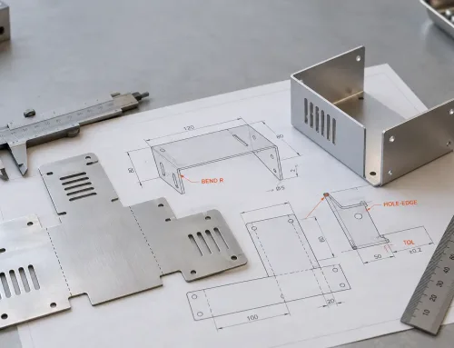
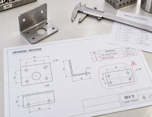
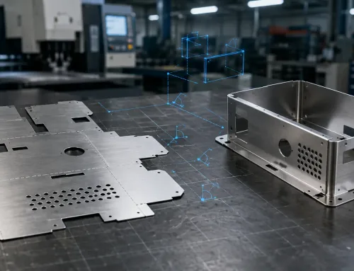
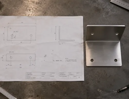
A technical drawing is a standardized, dimensioned document used to communicate the exact geometry, material, tolerances, and manufacturing requirements of a part or assembly to the manufacturer.
It provides a clear and universally understood graphical language for defining parts, along with a complete production specification. It also serves as a practical basis for cooperation between the buyer and the manufacturer.
For engineers, purchasing teams, and project managers involved in custom metal fabrication, understanding how to read, create, and evaluate technical drawings is an essential skill.
What Is a Technical Drawing?
A technical drawing, often also called an engineering drawing, is a formal technical product document created according to recognized standards such as ISO 128, ISO 5456, ISO 8015, ISO 2768 / ISO 22081, or the ASME Y14 series. Among these, ASME Y14.5 is widely used for dimensioning, tolerancing, and GD&T notation.
Its main purpose is to define a complete manufacturing specification that is clear, unambiguous, standardized, and easy to interpret.
A CAD model provides the geometric shape of a part, but a technical drawing adds critical manufacturing information, such as material grade, surface finish requirements, critical and non-critical tolerances, thread specifications, and special process requirements.
Why Technical Drawings Still Matter in Modern Manufacturing
Although 3D modeling is now widely used, technical drawings remain indispensable in manufacturing for several reasons:
- They verify the digital design before production starts, helping catch errors that may be missed during model review alone.
- They serve as a contractual reference in procurement. When a drawing and a 3D model conflict, the drawing is often treated as the controlling document.
- They contain essential information for the manufacturing process flow that may not be included in the 3D model. For more detail on what 2D drawings and 3D CAD files each provide, see the later section on 2D Technical Drawings vs. 3D CAD Files.
- They act as a universal language in global supply chains, independent of a specific software platform or file format.
Types of Technical Drawings
Technical drawings can be divided into several types depending on their purpose:
- Part Drawing — Defines all dimensions, tolerances, material specifications, and manufacturing requirements for a single component.
- Assembly Drawing — Shows how multiple parts fit together and usually includes a Bill of Materials (BOM).
- Exploded View Drawing — Separates components spatially to show assembly order and relationships between parts.
- Schematic Drawing — Shows functional relationships, commonly used in electrical or hydraulic systems rather than for precise geometry.
In sheet metal fabrication, the most commonly used drawing types are part drawings and assembly drawings.
Key Elements of a Technical Drawing
Title Block
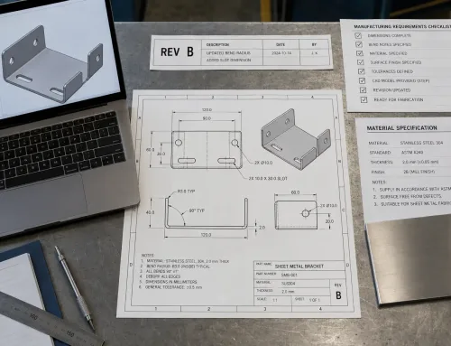
The title block contains essential metadata, including the drawing number, revision history, company name, scale, units, and general tolerance specifications.
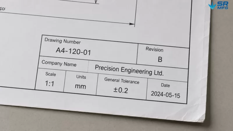
The actual appearance of a standard drawing title block, marking the key fields most frequently concerned by the procurement and engineering teams.
For purchasing teams, the completeness of the title block is one of the first indicators of drawing quality. Missing revision dates or unclear unit definitions are common causes of manufacturing errors.
Orthographic Views and Isometric Views
Most technical drawings use orthographic projection, a set of 2D views such as the front view, top view, and right-side view, to fully describe a 3D object.
First-angle projection, commonly used under ISO standards in Europe and Asia, and third-angle projection, commonly used under ASME standards in North America, arrange views differently. The projection symbol in the title block tells the reader which projection system is being used.
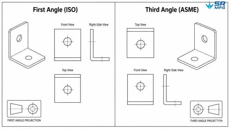
The view layout of the same sheet metal bracket part under two projection systems is displayed side‑by‑side for comparison, helping you intuitively understand the meaning of projection symbols.
An isometric view provides an intuitive 3D visual reference and helps improve understanding. However, it should not replace dimensioned orthographic views for manufacturing.
Dimensions and Tolerances
Every functional feature must be clearly dimensioned. Linear dimensions, angular dimensions, diameters, and radii should be marked in a way that is clear and unambiguous.
Tolerances define the acceptable variation for each dimension. Two common approaches are used:
- Linear tolerancing, such as 50.0 ± 0.2 mm, directly defines the upper and lower limits.
- Geometric Dimensioning and Tolerancing (GD&T) defines geometric controls relative to datums, such as flatness, parallelism, position, and profile.
GD&T is especially valuable for sheet metal parts, because bend accuracy and hole position relative to bend lines are often critical to assembly performance.
Surface Finish and Surface Roughness Symbols
Surface roughness symbols, such as Ra values, define the required quality of machined or formed surfaces.
Sheet metal surface finishing requirements specify post-processing needs, such as powder coating, anodizing, or electroplating. In sheet metal manufacturing, it is important to specify coating thickness on the drawing because plating or coating buildup can affect the final dimensional accuracy of the part.
Welding Symbols
Standardized welding symbols specify the weld type, size, length, and location. Common weld types include fillet welds, butt welds, spot welds, and plug welds.
For sheet metal assemblies that involve spot welding or seam welding, correct welding symbols help eliminate ambiguity and prevent costly rework.
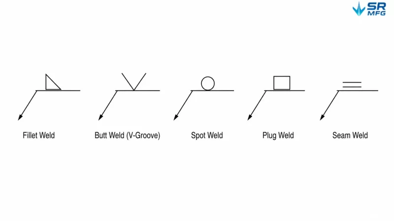
Deconstruct the structures and meanings of five common welding symbols in sheet metal drafting for use as a quick reference chart.
Material Notes
A technical drawing must specify the material grade and thickness, along with the applicable material standard.
Common material notes in sheet metal fabrication include stainless steel such as SUS304 or 316, cold-rolled steel such as SPCC or DC01, aluminum alloys such as AL5052 or AL6061, and galvanized steel such as SGCC.
Material thickness may be expressed in millimeters or gauge numbers, depending on regional practice.
Technical Drawing Standards
Two major standard systems are commonly used for technical drawings worldwide.
- ISO standards are widely used in Europe, Asia, and many international supply chains. Relevant standards include ISO 128 for drawing presentation, ISO 5456 for projection methods, ISO 8015 for tolerancing principles, and ISO 22081:2021 for general tolerances.
- ASME Y14.5 is the primary standard used in North America. Key differences between ISO and ASME systems include projection methods, tolerancing philosophy, and default handling of geometric tolerances, including ASME Rule #1.
- Regional standards, such as JIS B 0001 in Japan and GB/T standards in China, are largely aligned with the ISO system.
When sourcing sheet metal parts internationally, buyers and engineers should always confirm the applicable standard system and make sure that the projection symbol, tolerance notes, and drawing conventions match that system.
Technical Drawings in Sheet Metal Manufacturing
Flat Pattern
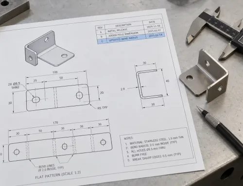
A sheet metal flat pattern is the 2D blank shape of a part before bending. It is one of the most critical elements in a technical drawing because it defines the cutting size of the raw material, which directly determines the laser cutting or punching program.
A flat pattern typically includes bend lines, bend direction arrows, and bend deduction values calculated from material thickness and the K-factor. Even when a 3D STEP file is provided, manufacturers still need the flat pattern to verify the unfolding calculation and confirm the exact cutting dimensions.
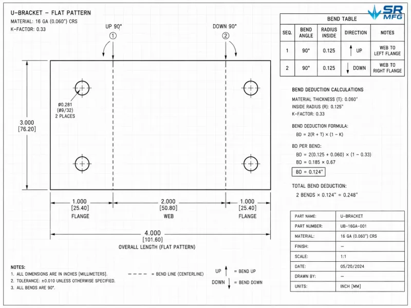
The actual marking method of a sheet metal development drawing, including bending lines, bending direction arrows, dimension markings and bending tables.
Bend Notes and Bend Tables
Sheet metal bending requirements should specify the bend angle, bend radius, and bend direction. Common annotations include bend-up and bend-down arrows, as well as dimensions taken to the mold line or radius centerline.
A bend table summarizes all bend-related parameters, such as angle, radius, direction, and bend sequence, in a single reference table. This is especially useful for sheet metal parts with multiple bends.
Sheet Metal-Specific Tolerances
Sheet metal tolerances are different from machined-part tolerances. Typical laser-cut linear dimensions can often achieve around ±0.1 mm, while bend angles are commonly controlled within ±0.5° to ±1°, depending on the material, thickness, tooling, and process conditions.
Hole positions relative to bend lines are especially sensitive. Features placed too close to the bend area may deform during forming. Designers should refer to ISO 2768-mK for general linear and angular tolerances, or use ASME Y14.5 to define critical tolerances individually.
Surface Finish and Hardware Notes
Sheet metal parts often require post-processing, such as powder coating, anodizing, electroplating, brushing, or passivation. Each process can add dimensional buildup. For example, powder coating may add approximately 0.06–0.12 mm per side.
The drawing should clearly specify the finish type, color, coating thickness, and applicable standard. For custom sheet metal parts with self-clinching hardware, such as lock nuts, standoffs, and studs, commonly PEM-type components, the drawing should identify the part number, thread specification, and installation location.
How Drawing Quality Affects Quotation, Lead Time, and Cost
A complete and clear technical drawing is one of the most important factors in obtaining a fast and accurate sheet metal quotation.
Incomplete drawings, such as drawings with missing dimensions, vague tolerances, or no surface finish specification, force manufacturers to ask repeated clarification questions. This extends the quotation cycle and wastes valuable time for both sides. Unclear material notes may also lead to incorrect material pricing.
Another issue that requires special attention is over-tolerancing. Excessively tight tolerances can increase cost by requiring slower processing, stricter inspection, or secondary machining. For example, specifying ±0.05 mm on a non-critical mounting hole when ±0.2 mm would fully meet the functional requirement can unnecessarily increase production cost and reduce manufacturing efficiency.
Manufacturer’s Drawing Review Checklist
To support smooth quotation and production, make sure your technical drawing includes the following information:
- A complete title block with part number, revision, material, and surface finish
- All critical dimensions and clear tolerances, including a flat pattern with bend notes for sheet metal parts
- Surface finish notes, hardware notes, material grade, thickness, and applicable standards
- Welding requirements, part marking, packaging requirements, and sheet metal inspection requirements
Common Mistakes in Technical Drawings for Sheet Metal Parts
- Incorrect dimensioning — Examples include dimensioning to theoretical sharp corners instead of tangent points, or using chain dimensions that create tolerance stack-up. These are common causes of manufacturing defects.
- Manufacturability errors — These include specifying a flange height that is too short for the bend radius, placing holes too close to bend lines, or applying tolerances beyond the capability of the forming process.
- Documentation errors — Outdated revisions, mixed metric and imperial units on the same drawing, or missing projection symbols can create confusion during production and inspection.
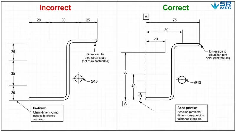
Compare and demonstrate two common dimensioning errors in sheet metal drafting and their correct practices to help designers and purchasers conduct quick self‑inspections.
2D Technical Drawings vs. 3D CAD Files
Both 2D drawings and 3D CAD files are essential.
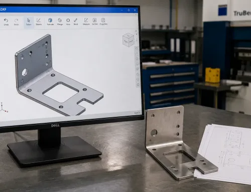
A 3D model defines geometry, spatial relationships, and supports flat pattern development and interference checks. A 2D technical drawing defines tolerances, surface finish, material specifications, notes, welding requirements, and most importantly, the contractual manufacturing requirements used in procurement.
Common exchange formats include:
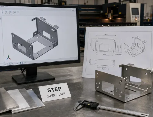
- STEP (.stp) for universal 3D geometry
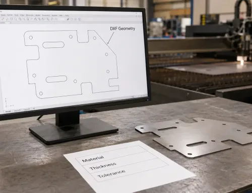
- DXF for 2D flat pattern cutting data
- PDF for dimensioned technical drawings
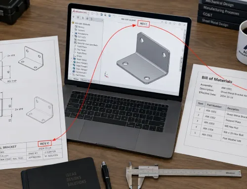
For sheet metal orders, the best practice is to provide a complete data package that includes the STEP file, PDF drawing, and DXF flat pattern file.
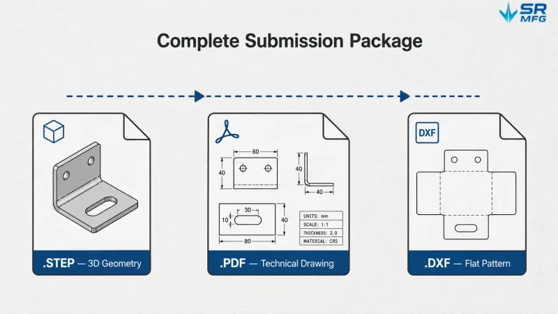
STEP 3D files, PDF drawing files, and DXF unfolding files.
Technical Drawing and Related Terms
| Term | Meaning |
|---|---|
| Technical Drawing | A formal, standardized, dimensioned manufacturing document |
| Engineering Drawing | Often used interchangeably with technical drawing; the exact meaning depends on context |
| Blueprint | A historical term from the cyanotype printing process; now commonly used to refer to any technical drawing |
| Technical Sketch | A hand-drawn, informal, conceptual drawing that may not be dimensioned or standardized |
| CAD Drawing | A digital output created in CAD software; a technical drawing defines the information standard it should follow |