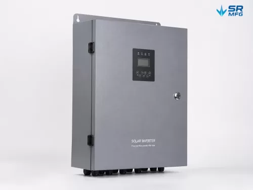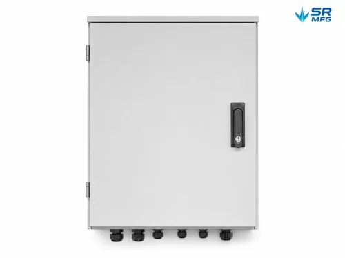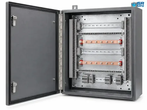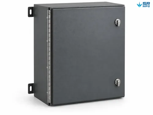
Electrical Distribution Cabinets
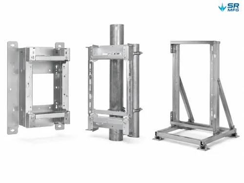
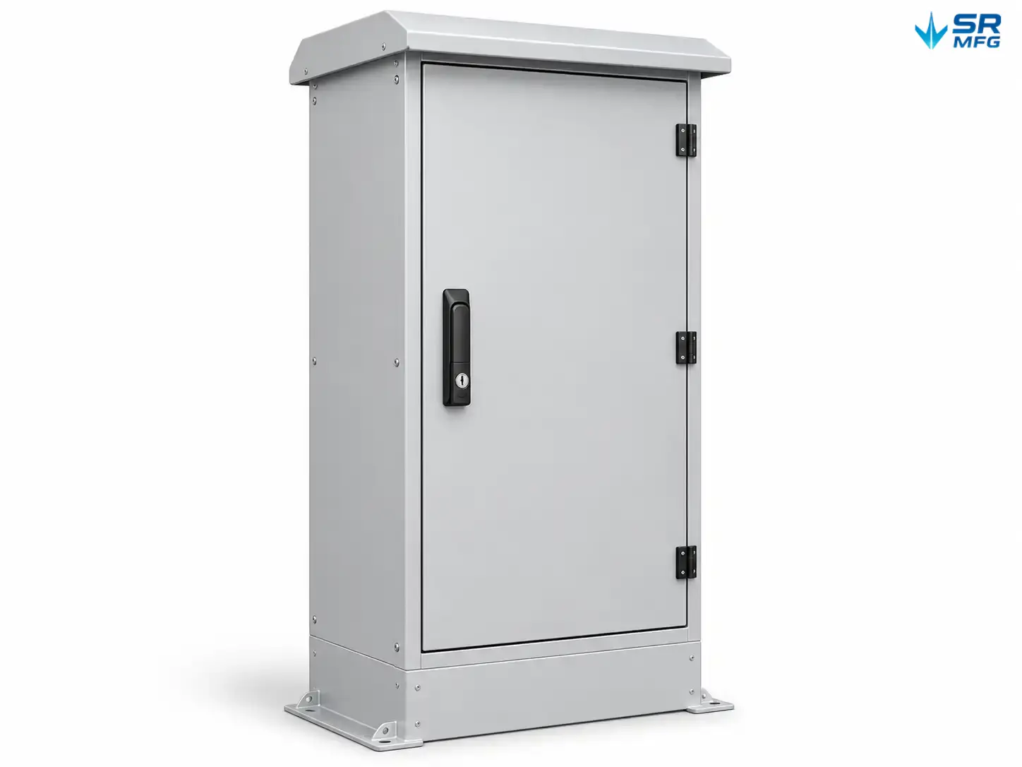
Custom-fabricated sheet-metal electrical distribution cabinets for low-voltage power distribution, metering, and feeder applications. Floor-standing, wall-mount, pole-mount, and flush-mount bodies built to your drawing.
- Construction: Laser-cut, CNC-bent, welded cabinet body with gasketed doors
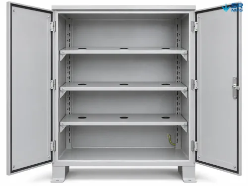
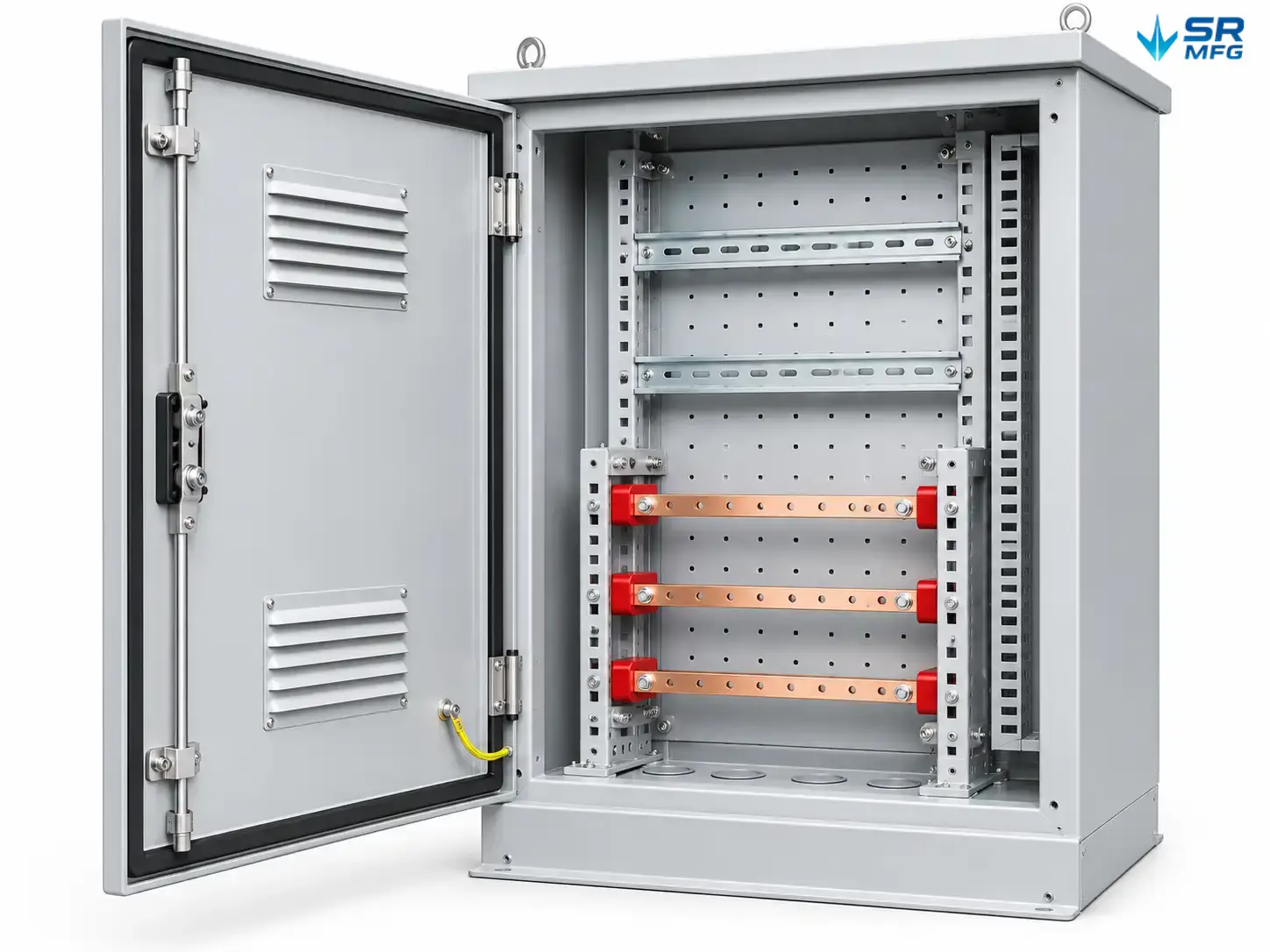
- Internal structure: Mounting plates, DIN-rail layouts, busbar supports, partition walls
- Materials: Cold-rolled steel, galvanized steel, stainless steel, aluminum alloy
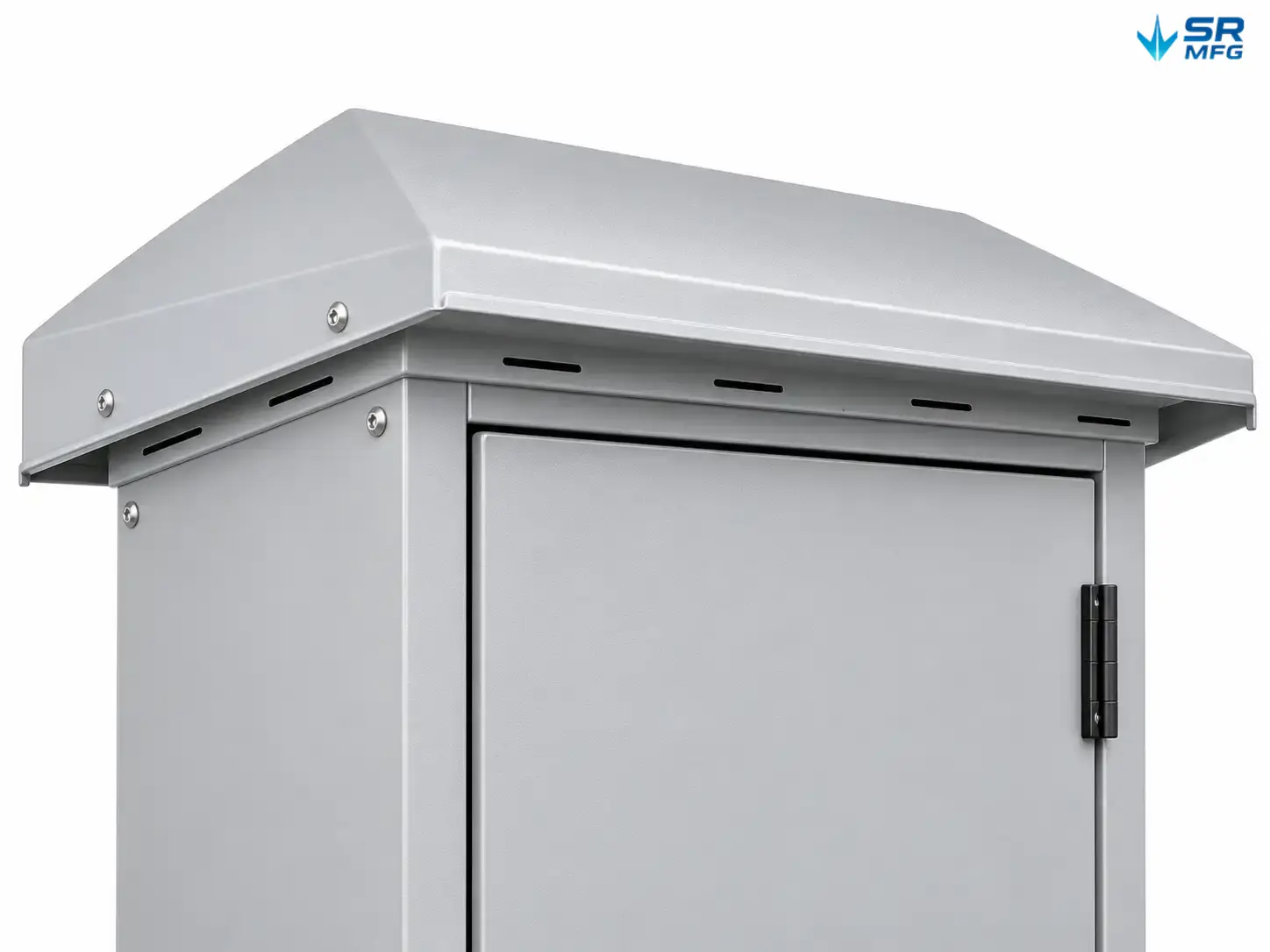
- Environmental design: Drainage roofs, condensation control, sealed cable entries
- Custom work: Dimensions, cutouts, locks, RAL finish, logo plates
- Order flow: Prototype to repeat production, inspection records on request
→ Send your drawing or key dimensions to request a fabrication quote.
Product Details
| Item | Specification |
|---|---|
| Fabrication processes | Laser / punch cutting, CNC bending, welding (spot, MIG, TIG), riveting, drilling, tapping, deburring |
| External dimensions | Custom H × W × D to drawing; standard size families available |
| Sheet thickness | Common fabrication window approx. 0.8–3.0 mm; heavier structural sections by design |
| Dimensional tolerance | Per drawing; standard sheet-metal tolerances where not specified |
| Mounting plate | Removable or fixed; thickness and hole pattern to component layout |
| Busbar support spacing | Set to busbar arrangement and mechanical stress requirements (per project) |
| Door configuration | Single / double door; removable or hinged; opening angle per design |
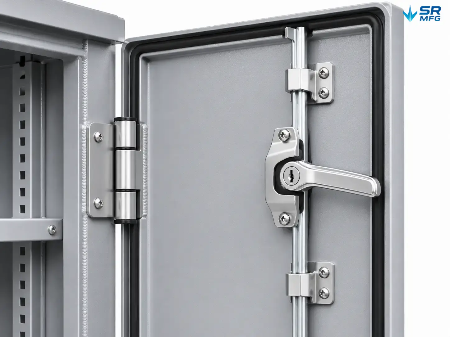
| Locking options | 3-point handle, triangular lock, round lock, padlock hasp, tamper-resistant fasteners |
| Gasket material | EPDM or silicone (environment-dependent) |
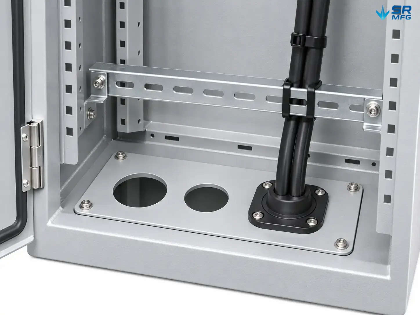
| Cable entry | Gland plates, knockouts, or sealed feed-through modules — top, bottom, or side |
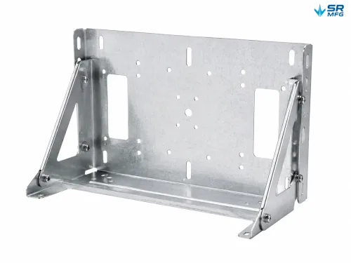
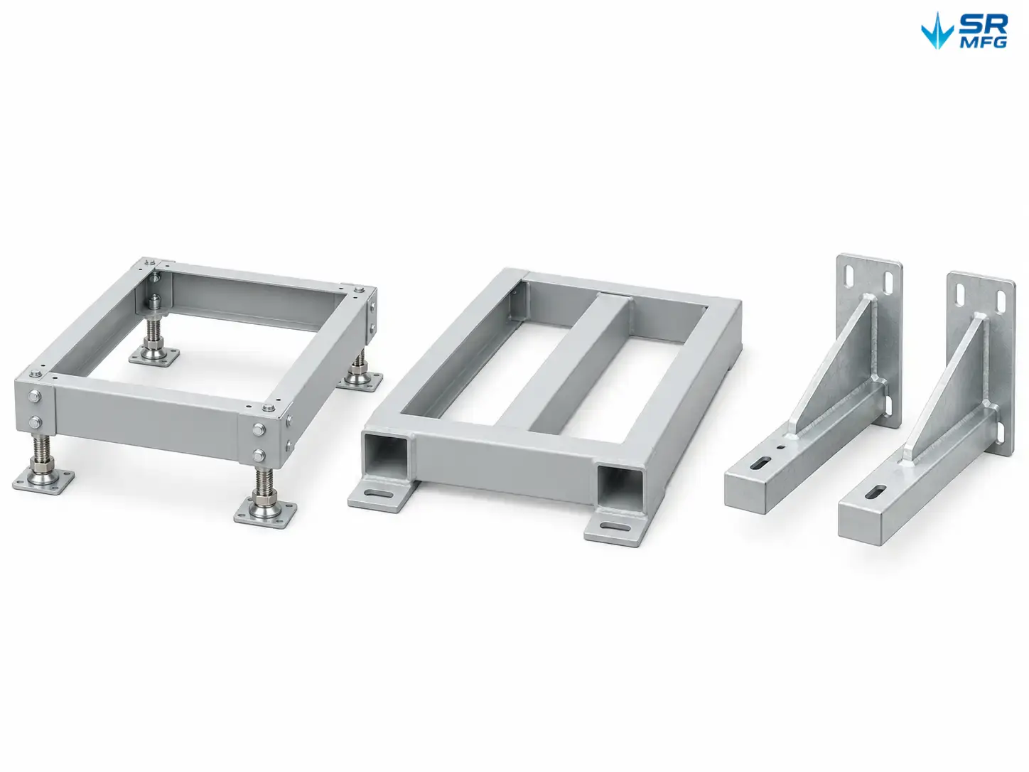
| Base / anchoring | Fixed plinth, adjustable base, channel-steel base, wall brackets, pole-mount hardware |
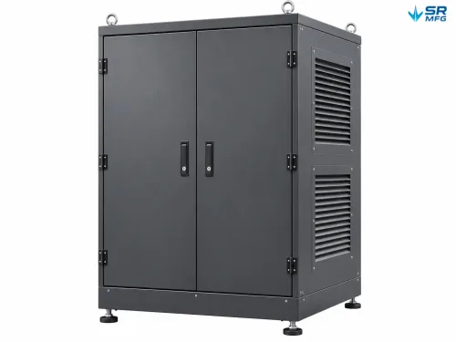
| Ventilation | Louvers, filter units, fan kits, thermal accessory cutouts |
| Temperature range | Design options for standard indoor, outdoor, and extended climate (per project) |
| Finish thickness | Powder coating film thickness per project specification |
| Grounding provision | Grounding studs on the body, equipotential bonding points on doors |
| Inspection | Dimensional check, coating adhesion, gasket fit, hardware function, packing completeness |
| Documentation | Inspection records; material certificates on request |
| Assembly support | Optional pre-installation of mounting plates, busbar supports, wiring channels |
| Marking | Silkscreen, laser marking, engraved or embossed nameplates |
Product Overview & Supply Scope
We fabricate the cabinet body and internal structure of electrical distribution cabinets — the sheet-metal shell that houses and protects low-voltage distribution equipment. Every unit is built to your drawing or a confirmed project layout.
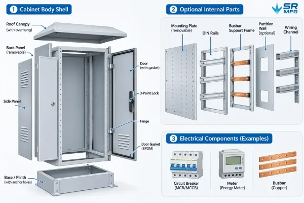
An exploded view of a distribution cabinet separating three groups: the cabinet body and doors included in supply, optional mounting plates and busbar supports, and electrical components such as breakers and meters that are not included.
| Supply Scope | Content |
|---|---|
| Included | Cabinet body, doors, roof, base, lock hardware, gaskets, grounding provisions, mounting plate or rail structure, cable entry preparation |
| Optional | Busbar support frames, partition walls, ventilation units, pre-installed wiring channels, factory assembly support |
| Not included | Circuit breakers, fuses, meters, busbars, contactors, and other electrical components — supply them separately or send them to us for pre-assembly |
A clear supply boundary keeps quoting clean: you get a cabinet engineered around your component layout, not a finished switchgear assembly.
Application Scenarios
Distribution cabinet bodies serve wherever incoming power must be split, metered, and routed to feeders.
- Residential and commercial compounds — floor-standing or wall-mount feeder and sub-distribution cabinets near transformer rooms
- Utility metering installations — partitioned cabinets with a sealed metering bay and a separate distribution section
- Industrial plants — workshop main distribution cabinets with busbar supports and large cable entries for machine feeders
- Outdoor cable distribution points — pole-mounted or ground-mounted bodies with drainage roofs for street and roadside networks
- Infrastructure and equipment rooms — flush-mount and wall-mount cabinets for control and distribution panels
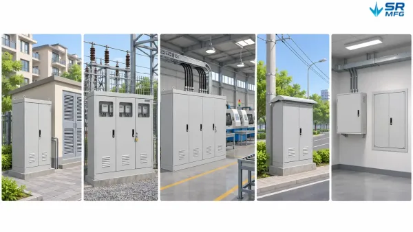
A five-panel scene grid: distribution cabinets at a residential compound, a utility metering installation, an industrial workshop, an outdoor pole-mounted cable distribution point, and a wall-mounted cabinet in an equipment room.
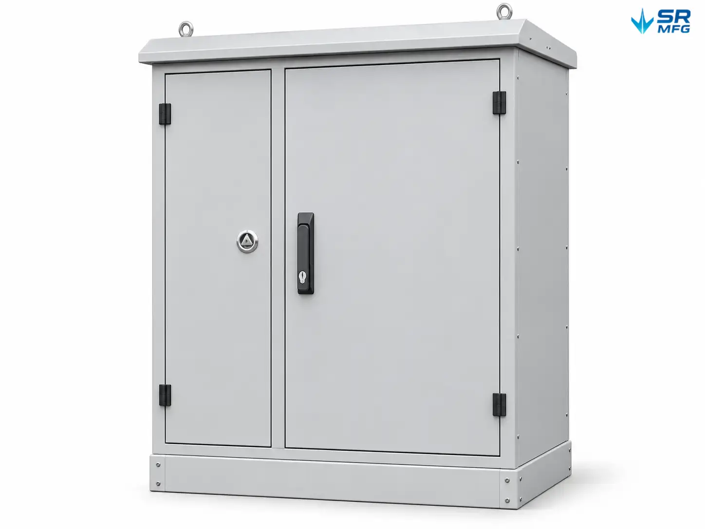
Scenario example: a housing project needs metering and feeder protection in one footprint. A partitioned double-door cabinet separates the sealable metering bay from the distribution section. Both doors share one frame, one roof line, and one set of mounting provisions — less site work, cleaner inspection.
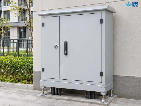
A partitioned double-door cabinet installed at a housing project: a sealable metering bay on the left and a distribution feeder section on the right, sharing one frame and canopy.
Cabinet Body Construction
The cabinet body carries mechanical load, weather exposure, and daily access. Structure follows the application.
- Frame and panel work: Sheet-metal panels formed on CNC brakes; welded or riveted frames depending on size class. Larger floor-standing bodies get internal stiffeners so doors stay aligned after transport and anchoring.
- Doors: Single or double, removable for site wiring. Door inner panels carry reinforcement around locks and hinges. Opening angle and swing direction follow the drawing.
- Roof and canopy: Overhanging roof sections on outdoor models. Drainage channels and drip edges move water away from the door seals.
- Base and anchoring: Fixed plinths, adjustable bases, or channel-steel frames. Anchor hole patterns match your foundation drawing.
- Locking hardware: 3-point handles on tall doors, triangular or round locks for utility sealing practice, padlock hasps for shared-access sites.
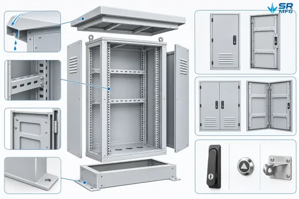
A structural breakdown of a distribution cabinet body showing the formed panel frame, removable doors with inner reinforcement, overhanging drainage canopy, plinth base, and locking hardware as separate labeled groups.
Internal Mounting & Wiring Structure
Internal structure is set to your component layout — these fabrication details decide how long installation takes on site.
- Mounting plates: Removable or fixed plates with hole patterns to your layout. Plate thickness scales with component weight.
- DIN-rail and modular layouts: Rail positions for modular devices; adjustable cross-members for mixed layouts.
- Busbar support frames: Support spacing and insulation mounting set to your busbar arrangement and mechanical stress requirements.
- Partition walls: Full partitions with separate doors — standard for metering-plus-distribution cabinets where one bay must stay sealable.
- Cable entry and routing: Gland plates or knockouts at top, bottom, or sides. Sealed feed-through modules for outdoor bodies. Internal wiring channels and terminal-mount areas on request.
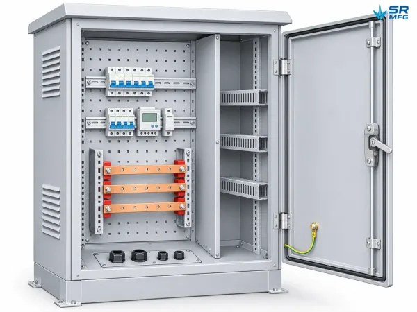
An open-cabinet interior view showing a removable mounting plate with hole pattern, DIN-rail rows, insulated busbar support frames, a partition wall section, and cable routing channels with a bottom gland plate.
Scenario example: an industrial plant runs heavy feeder cables in from below. The cabinet uses a bottom gland plate with pre-cut entries, a reinforced cable support bar above the plate, and a removable mounting plate so the electrical team can wire the unit before it reaches site.
Materials & Surface Protection
Choose material and finish against the environment, not by habit.
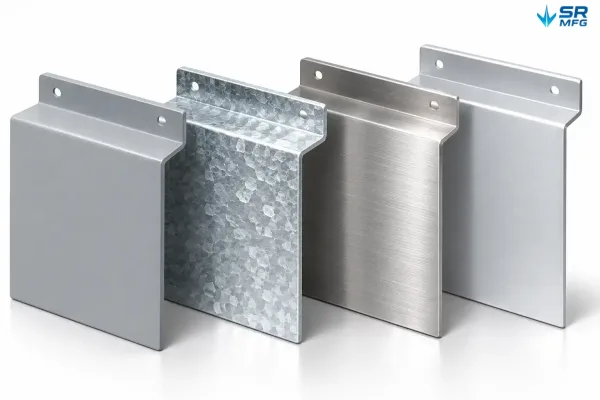
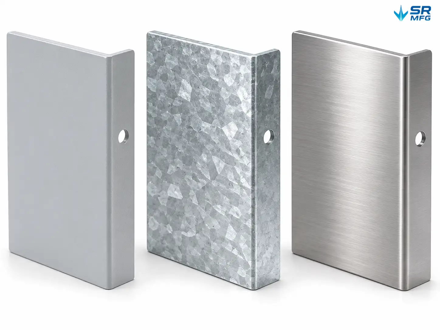
Four cabinet panel samples in a row: powder-coated cold-rolled steel, hot-dip galvanized steel, brushed stainless steel, and anodized aluminum, each with a folded edge.
| Requirement | Typical Solution |
|---|---|
| Indoor distribution, paint-grade finish | Cold-rolled steel with powder coating in your RAL color |
| Outdoor exposure — rain and humidity | Galvanized steel body, or coated steel with enhanced sealing and drainage |
| Coastal, chemical, or washdown areas | Stainless steel (SUS304 / SUS316) with matched gasket selection |
| Weight-sensitive or non-magnetic enclosures | Aluminum alloy with anodized or coated finish |
| High-traffic or vandal-prone sites | Thicker gauge panels, reinforced door frames, tamper-resistant fasteners |
Powder coating runs in custom RAL colors with film thickness controlled to project spec. Hot-dip galvanizing suits outdoor bodies where coating damage during installation is a real risk. Nameplates, logo plates, and circuit labels can be engraved, embossed, or silkscreened.
Ingress Protection & Environmental Design
Protection is a structure problem before it is a label. We design the sealing path first, then confirm the rating against your project requirements.
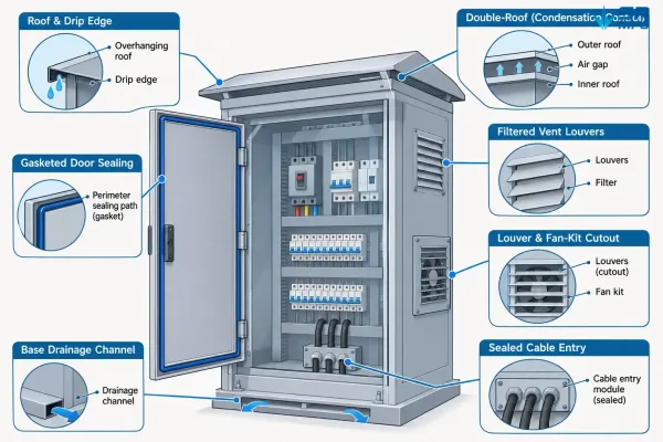
An annotated cabinet diagram showing the sealing path around the door gasket, overhanging roof with drip edge and drainage channel, filtered vent openings, and thermal accessory cutouts responding to rain, dust, condensation and heat.
| Environmental Challenge | Design Response |
|---|---|
| Driving rain | Overhanging roof, drip edges, sloped surfaces, gasketed door perimeter |
| Standing water and condensation | Drainage channels in the base, double-roof or ventilated canopy options, condensation control details |
| Dust and airborne particles | Full-perimeter gaskets (EPDM or silicone); filter vents on ventilated cabinets |
| Corrosive atmosphere | Material and finish upgrades — stainless body, enhanced coating, sealed entries |
| Heat build-up from housed equipment | Louvers, filter fan units, or cutouts for thermal accessories |
Protection targets (IP-class requirements for outdoor service, for example) are confirmed per project through design and, where required, test support. Sealing design also accounts for door-removed states and accessory openings, so field modifications do not void the intended rating.
Custom Fabrication Capabilities
Distribution cabinets rarely come off a shelf. This workflow keeps non-standard work predictable:
- Requirement review — send drawings, sketches, or key dimensions. We check manufacturability and flag design risks early.
- Engineering confirmation — hole patterns, cutouts, door hardware, gasket scheme, and finish spec are confirmed before tooling.
- Sampling — prototype or first article for fit check against your components.
- Production — repeat batches on the same process route with inspection records.
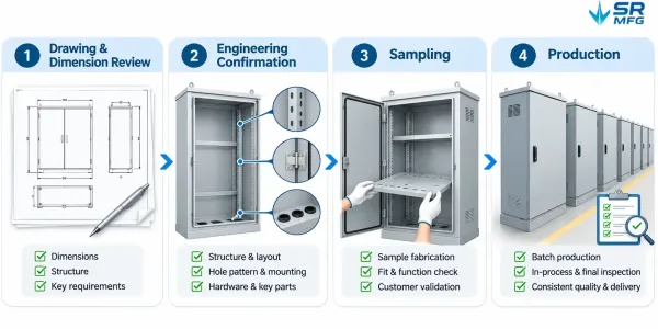
A four-step process strip: drawing and requirement review, engineering confirmation of holes and hardware, prototype sampling and fit check, then repeat production with inspection records.
Custom scope covers external dimensions, cable entry positions and sizes, viewing windows, special locks, internal bracket sets, busbar support spacing, partition positions, paint codes, and marking. OEM and ODM work is standard practice for us.
Scenario example: a system integrator needs 40 cabinets across three site layouts. One base design with three cutout variants keeps tooling simple and unit cost down — all variants share the same frame, door, and finish process.
Manufacturing & Inspection Brief
Bodies move through laser or punch cutting, CNC bending, welding or riveting, hardware installation, surface treatment, and final assembly. Each stage has a check point.
- Dimensional check against drawing on first article and at defined process intervals
- Coating inspection — film thickness and adhesion on finished surfaces
- Hardware and gasket fit — door alignment, lock function, seal continuity
- Accessory completeness — plates, brackets, gland plates, and fasteners per packing list
- Records — inspection reports, and material certificates on request
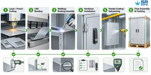
A fabrication flow from laser cutting and CNC bending through welding, hardware installation and surface treatment to final assembly, with inspection checkpoint marks at each stage.