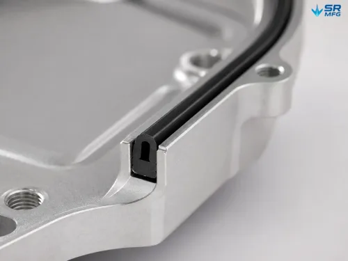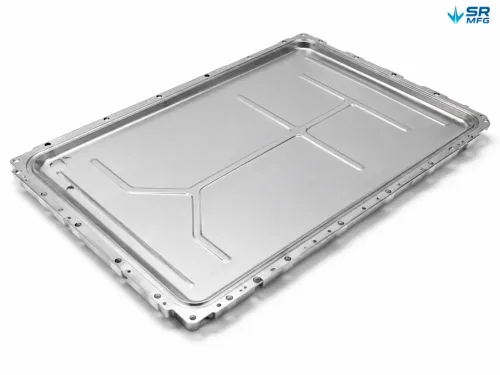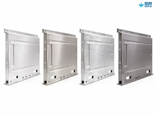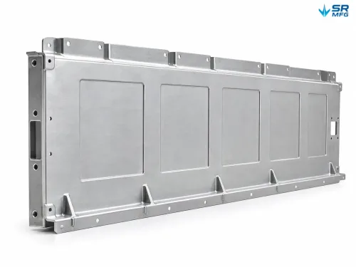
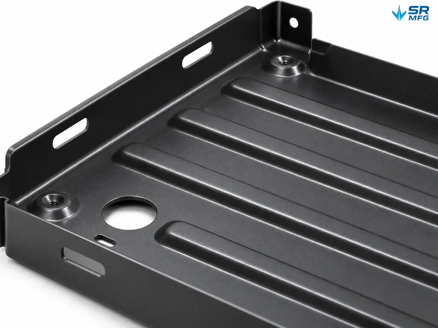
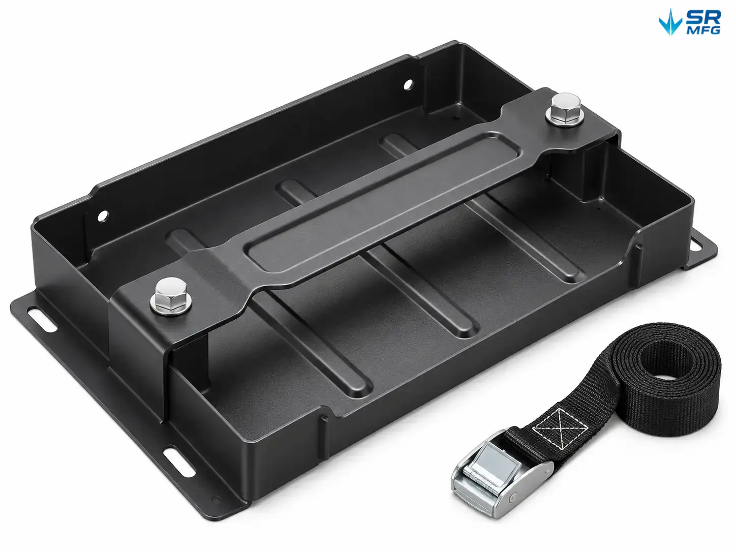
Battery Module Mounting Trays
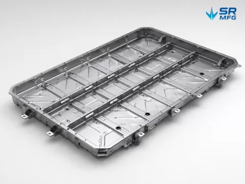
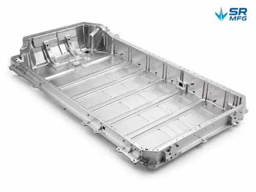
Custom battery module mounting trays fabricated from sheet metal to your module envelope and mounting interface. Designed for EV battery packs, energy storage cabinets, and UPS systems, they keep modules fixed in position, maintain required electrical clearance, and support straightforward installation and service.
- Secure module retention: formed flanges and hold-down interfaces engineered against your project’s vibration and transport loads.
- Battery-safe clearance: recessed fastener seats and formed edges keep hardware clear of cell cases.
- Material and finish options: cold-rolled steel, galvanized steel, stainless steel, or aluminum; powder coating, zinc plating, anodizing, or e-coating.
- Made to drawing: module envelope, hole pattern, fixing method, and insulation features customized per project.
- Flexible delivery scope: tray only, or complete kits with fasteners and insulation components.
Send your module dimensions or drawing to receive a quotation with DFM (design for manufacturability) feedback.
Product Details
| Parameter | Value / Basis |
|---|---|
| Product type | Formed sheet metal battery module mounting tray |
| Manufacturing mode | Made to drawing / Made to sample / Joint development |
| Module envelope (L × W × H) | Custom — provide module dimensions or drawing |
| Material options | Cold-rolled steel, galvanized steel, stainless steel, aluminum alloy |
| Sheet thickness | Selected per load and stiffness requirement; confirmed at quotation |
| Rated static load | Defined per project; load rating available on request |
| Structural features | Clearance recesses, flanged edges, formed ribs, cable pass-throughs |
| Mounting holes | Hole diameter, pitch, slot position, and thread type per drawing |
| Fixing method | Hold-down plate and bolts / strap tie-down / snap-in clips / bonded interface |
| Insulation option | Insulated pad seat, insulating coating, or insulated cover |
| Installation orientation | Horizontal, vertical, side-mount, pull-out serviceable |
| Surface finish | Powder coating (color options), zinc plating, anodizing, e-coating |
| Tolerance class | ISO 2768 general tolerances unless the drawing specifies otherwise |
| Fabrication processes | Laser cutting / CNC punching, bending, welding or riveting, tapping, hardware insertion |
| Inspection | Key dimension check, coating adhesion, visual; salt spray or insulation test optional |
| Unit weight | Approximate; varies with material and thickness — confirmed per final design |
| Delivery scope | Tray only / tray + fasteners / tray + fasteners + insulation components |
| Part marking | Part number, label, or logo stamping (optional) |
| Packaging | Per-piece protection, bulk, or custom packing per project |
| Drawing formats | STEP / DXF / PDF with key dimensions and tolerances |
| MOQ & lead time | Flexible, confirmed per project; prototypes supported |
Product Overview
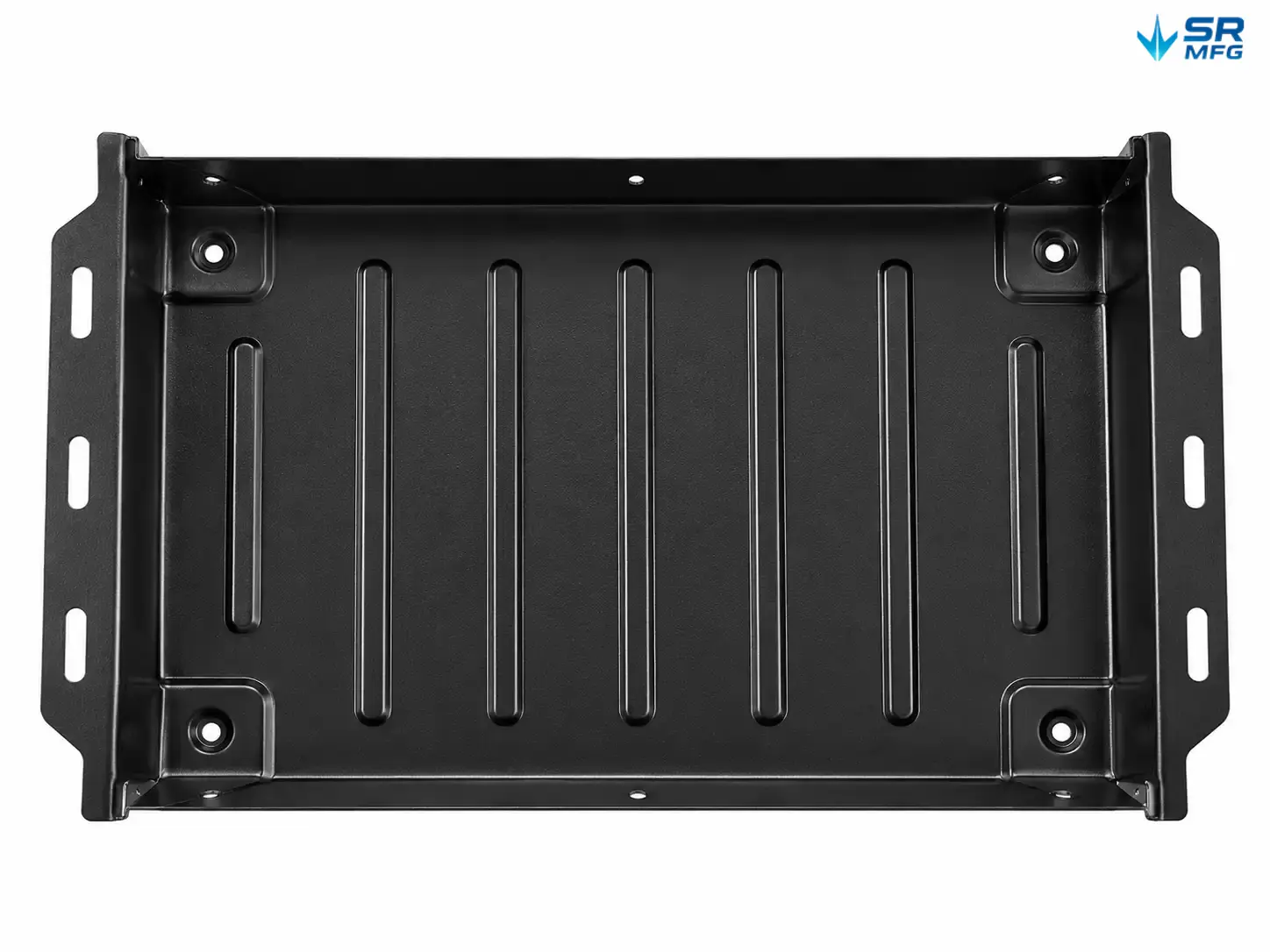
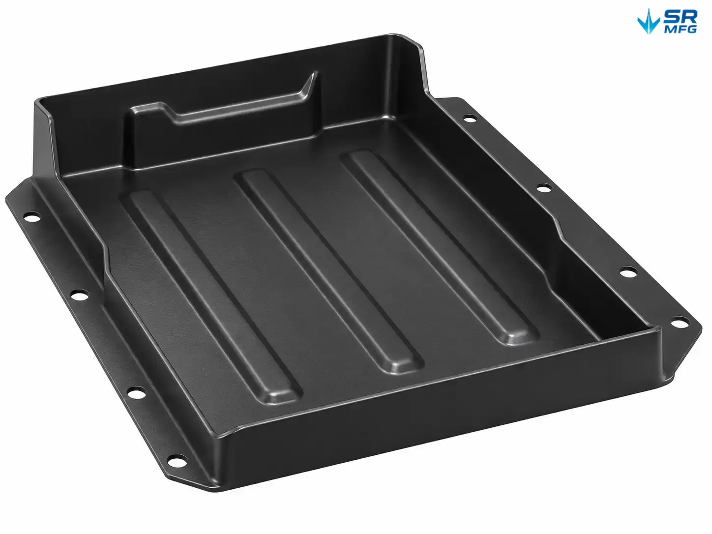
A battery module mounting tray is a formed sheet metal structure that fixes each battery module inside a pack or cabinet. It carries module weight, holds module position under vibration and shock, maintains electrical clearance to surrounding metal parts, and gives assemblers a clean interface for installation and service.
This is not a universal retail battery tray. Every tray is designed around a specific module envelope and mounting interface, so it fits on first assembly and carries the load case it was built for.
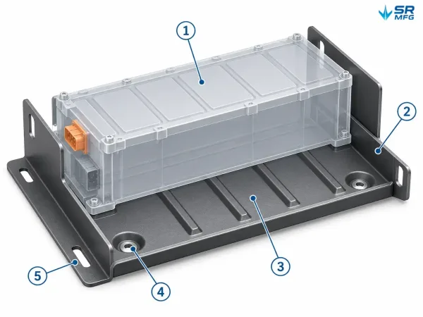
Annotated view of a formed sheet metal battery module tray with numbered callouts marking the module envelope, flanged edges, ribbed base, recessed fastener seats, and mounting interface.
| Function | What the tray does |
|---|---|
| Load-bearing | Supports module static weight and handling loads during service |
| Positioning | Locates modules on a repeatable pitch for stacked or array layouts |
| Isolation | Keeps fasteners and edges clear of cell cases and terminals |
| Service access | Allows module replacement without full pack disassembly |
Structural Design Highlights
Battery-Safe Clearance
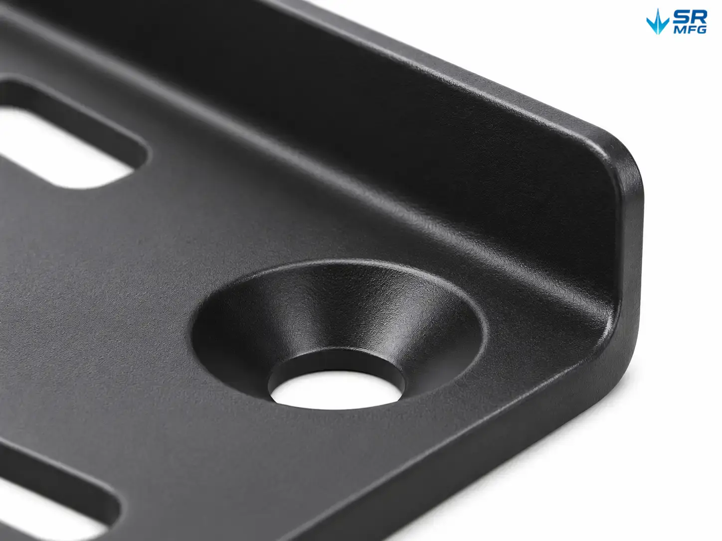
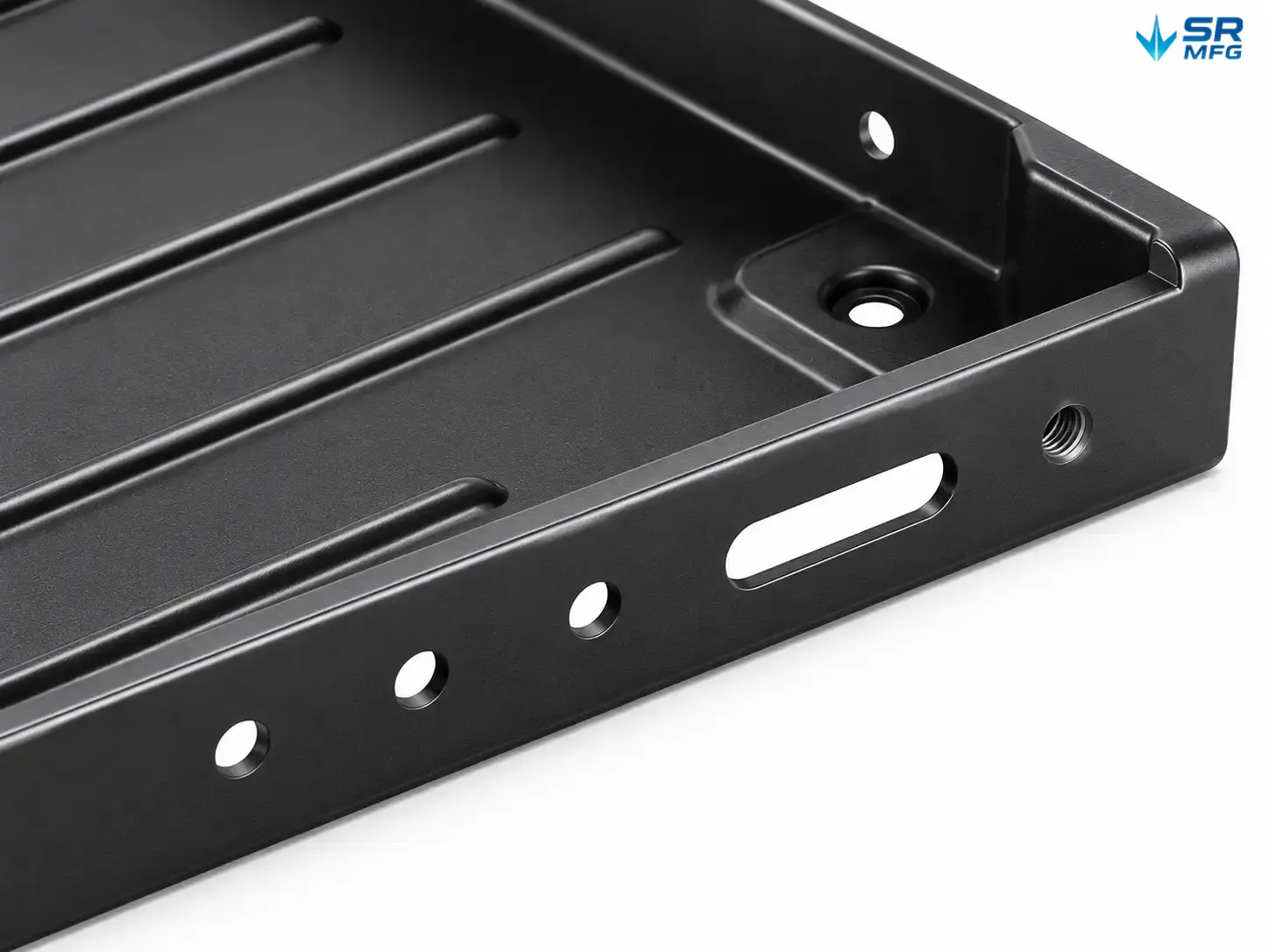
Fastener heads sit in recessed seats or below the module contact plane. Formed edges are hemmed or flanged away from cell cases. The goal is direct: no part of the tray touches a cell where vibration could wear through the case.
Flanges and Formed Ribs
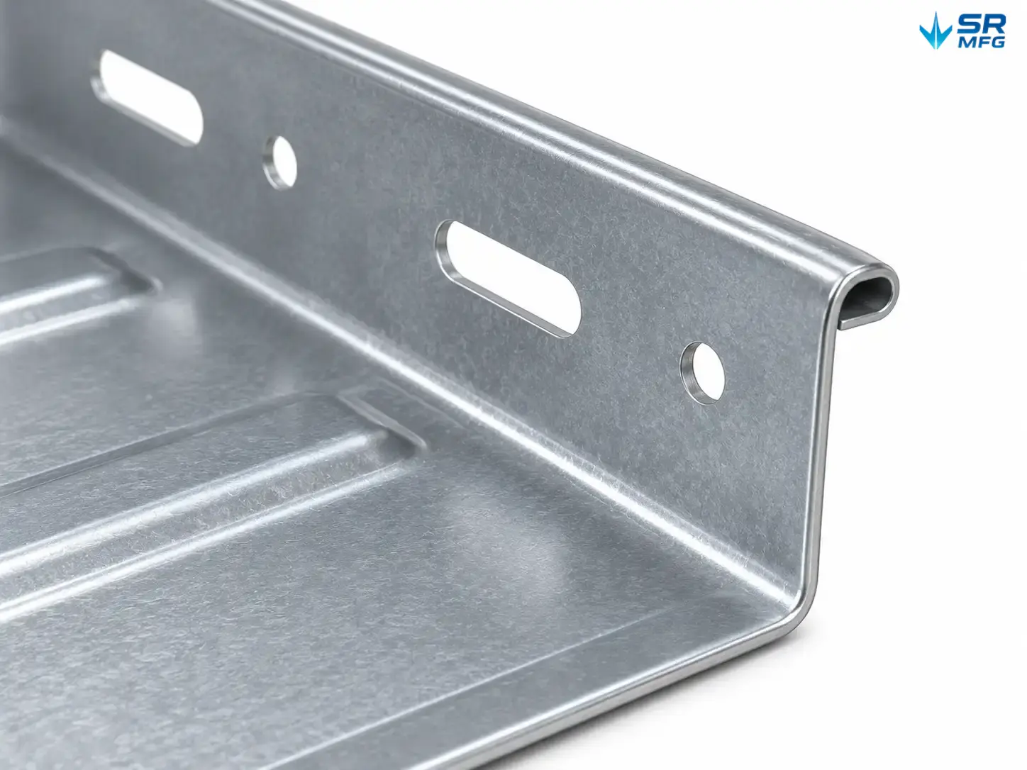
Load does not travel through flat sheet alone. Flanged edges and formed ribs raise stiffness without adding material thickness. That matters in weight-sensitive vehicle packs, and it helps stacked modules in cabinets where each tray carries the layers above it.
Mounting Holes and Interface
Hole pattern, slot geometry, and thread type are produced to your drawing. The interface to the pack frame or cabinet rail is a controlled dimension — not a universal slot.
Fixing Interfaces
Trays accept bolted hold-down plates, strap tie-downs, snap-in clips, or bonded interfaces. Contact faces are formed to spread clamp force and avoid point loading on the module case.
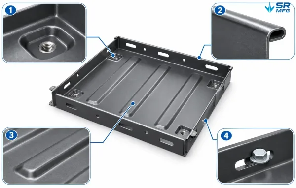
Combined detail view of a battery module tray showing a recessed fastener seat, hemmed edge, formed stiffening ribs, mounting slots, and a hold-down fixing face in one composition.
Application Scenarios
EV Battery Packs
Trays in vehicle packs face vibration, thermal cycling, and crash-load requirements. Typical build: cold-rolled or high-strength steel, powder-coated, with bolted hold-down plates and a ribbed floor. Mounting holes match the pack frame for line-side assembly.
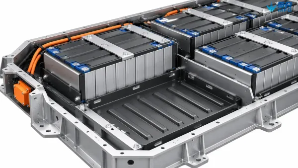
Cutaway view of an EV battery pack frame holding rows of battery modules seated in formed sheet metal mounting trays bolted to the pack structure.
Energy Storage Cabinets
Modules stack in arrays and may be replaced over system life. Typical build: trays with strap-type fixing and cable pass-throughs for sense wiring, oriented for pull-out service. Insulated pad seats are common where modules sit close to cabinet metal.
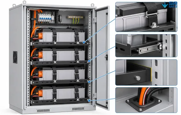
Cross-section of an energy storage cabinet showing stacked battery modules on pull-out sheet metal trays, strap tie-downs, cable pass-throughs, and insulation pads between trays and cabinet rails.
UPS and Backup Power
Backup systems run in equipment rooms and are serviced on a schedule. Typical build: horizontal trays with quick-release fixing, finished with e-coating or powder coat for indoor humidity. Part marking supports rack-level traceability.
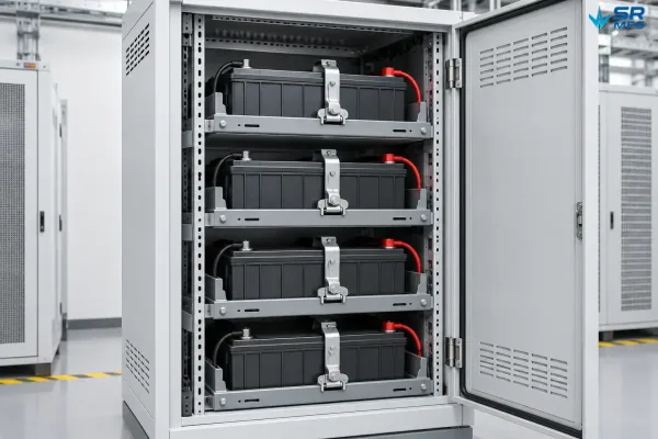
Equipment room rack with horizontal battery modules mounted on sheet metal trays, quick-release hold-down clamps, and part-marking labels on the tray edges.
Custom Engineering Process
- Drawing or requirement review: send module dimensions, expected loads, and interface details. Rough sketches are acceptable; STEP, DXF, or PDF is preferred.
- DFM feedback and quotation: we check bend feasibility, hole spacing, and fixing details, then quote material, finish, and delivery scope.
- Prototype and validation: first-article trays are built and fit-checked against your module and frame before production release.
- Production and inspection: batch fabrication with dimensional and coating inspection; inspection reports available on request.
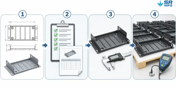
Horizontal four-step process diagram showing drawing review, DFM feedback and quotation, prototype validation, and production with inspection for a custom sheet metal tray project.
MOQ and lead time are confirmed per project. Prototype quantities are supported.
FAQs