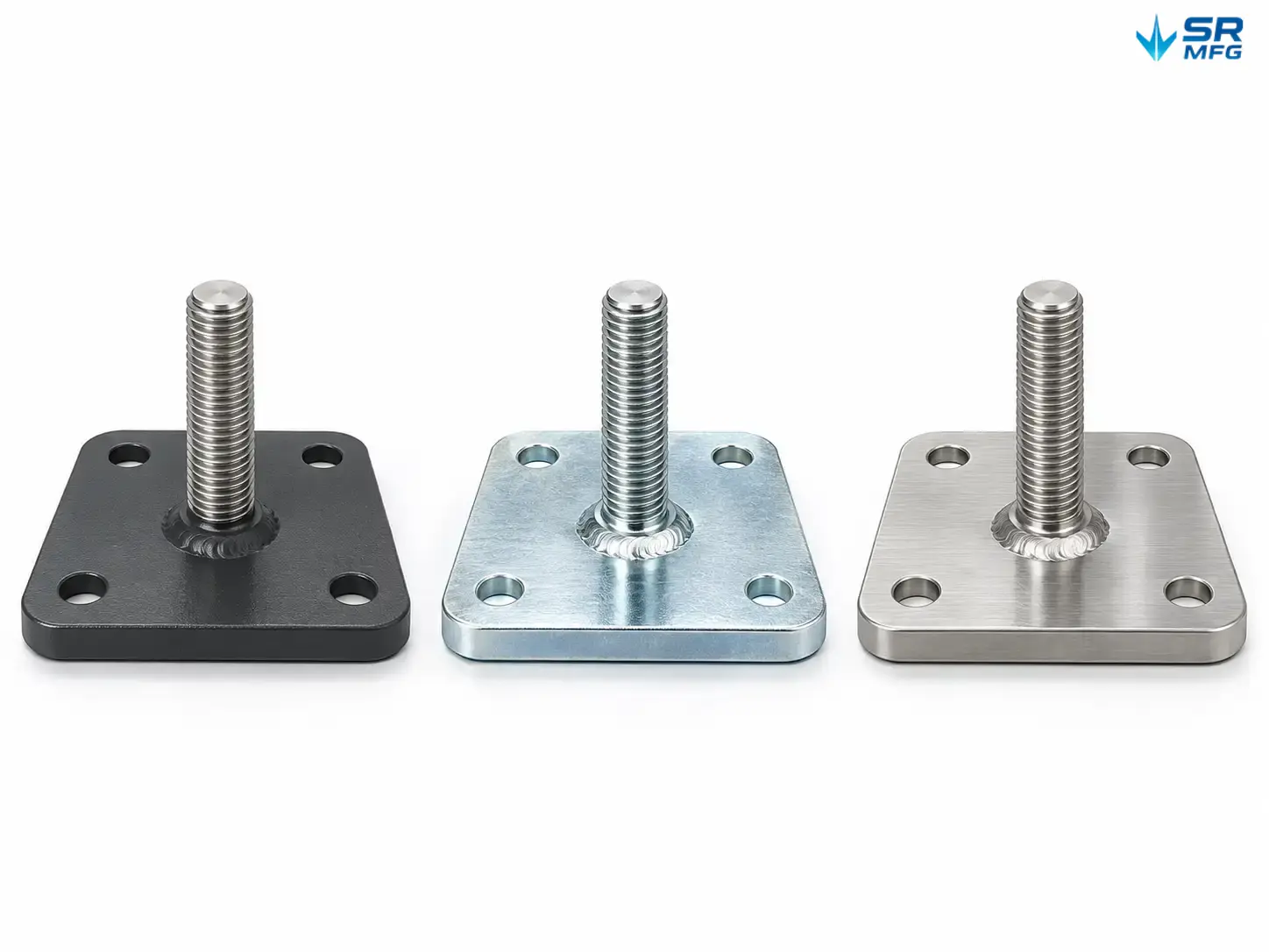
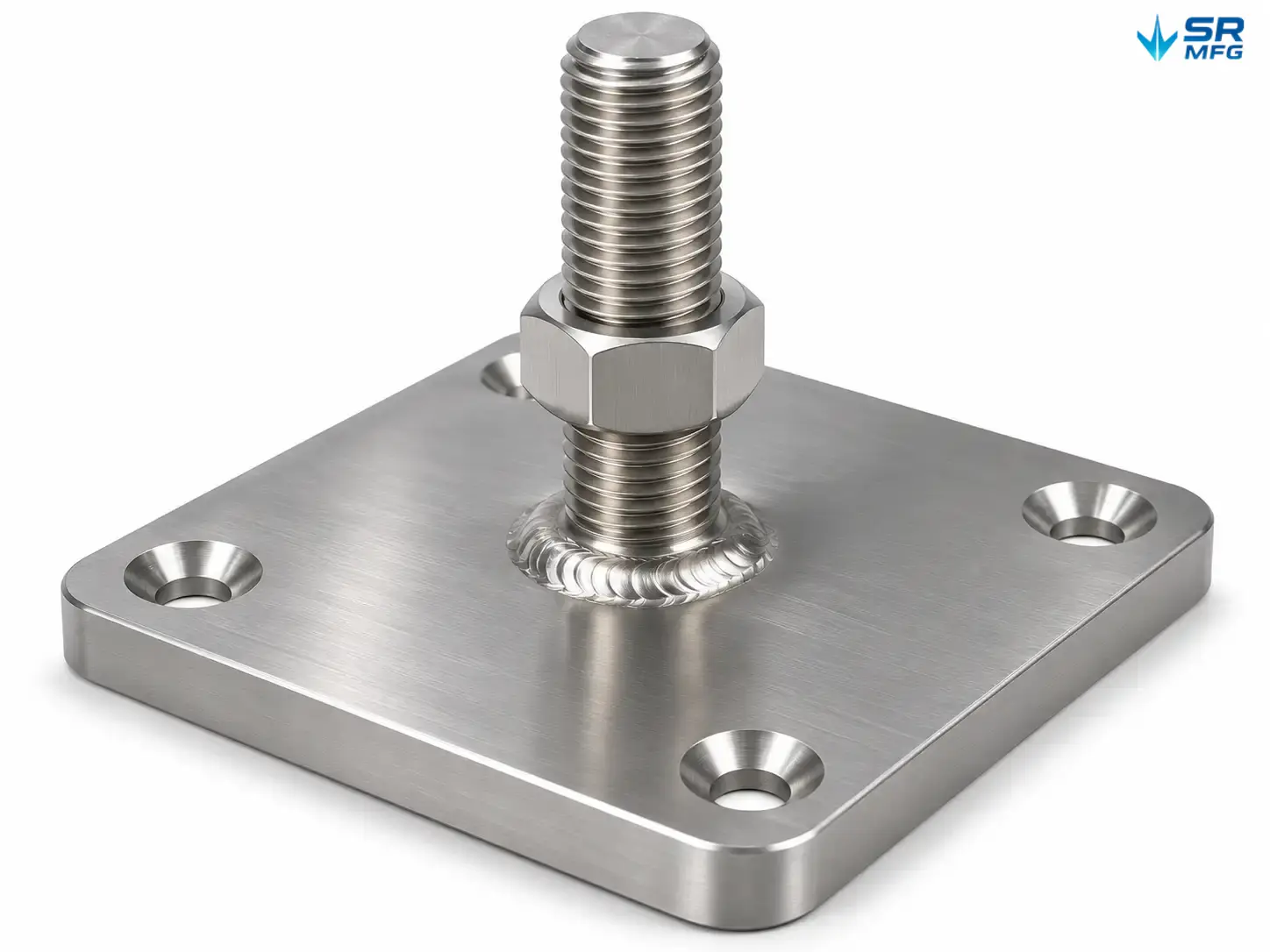
Equipment Leveling Base Plates
Laser-cut equipment leveling base plates for machine tools, industrial frames, and heavy equipment support. Available in carbon steel, galvanized steel, stainless steel, and aluminum with welded stud, tapped base, or threaded insert interfaces. Load classes from light bench equipment to heavy-duty machine foundations. Standard sizes ship from stock configurations; custom outlines, hole patterns, and stud lengths are fabricated to drawing. Request a quote with your equipment weight, base dimensions, or CAD file.
Product Details
| Specification | Detail |
|---|---|
| Product Type | Fabricated equipment leveling base plate |
| Base Material | Carbon steel / galvanized steel / stainless steel / aluminum |
| Plate Thickness | Selected by load class and span – confirmed per application |
| Base Outline | Round, square, rectangular, teardrop, or custom profile |
| Base Size | Small / Medium / Large standard bands; custom sizes to drawing |
| Thread Interface | Welded stud / tapped base / threaded insert |
| Thread Size | Metric and Inch ranges available |
| Stud Length | Standard and extended; cut to base thickness and travel requirement |
| Adjustment Method | Threaded leveling with jam nut lock |
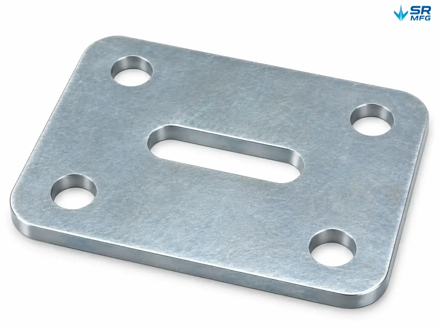
| Mounting Holes | Plain, bolt-through, countersunk, slotted, or custom pattern |
| Surface Finish | Powder coating, zinc plating, black oxide, passivation, or as specified |
| Anti-Slip Pad | Optional rubber or elastomer pad |
| Flatness | Standard fabrication tolerance; tightened on request |
| Hole Position Tolerance | Per drawing; laser-cut precision standard |
| Fabrication Process | Laser cut → form → weld or tap → finish → inspect |
| Inspection | Outline, hole position, thread gauge, visual coating check |
| Packaging | Bulk or per-set; export packing available |
| Prototype | Available for fit check before production |
| Production MOQ | Confirmed per project |
| Lead Time Basis | Quoted after drawing review and finish selection |
| Documentation | Dimensional report, material note, and finish confirmation on request |
What These Plates Do
Equipment leveling base plates sit between a machine base and the floor. They spread the load, compensate for uneven concrete, and provide a stable reference surface for precision equipment.
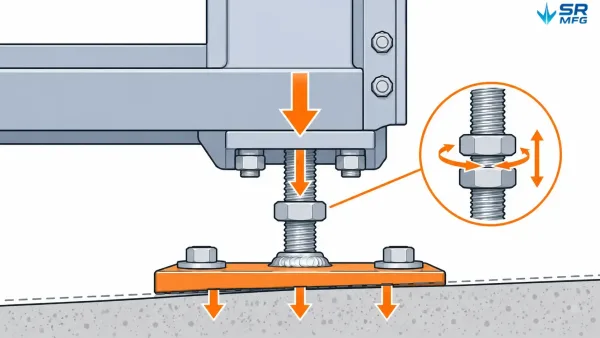
A cross-section diagram showing a leveling base plate placed between a machine foot and a concrete floor, with load arrows and height adjustment indicated.
Each plate is a fabricated metal component — cut from sheet or plate stock, formed where needed, and fitted with a threaded interface that accepts a leveling stud or adjustment screw. The result is a support point you can adjust, lock, and trust under sustained load.
Unlike cast leveling mounts, a fabricated base plate can be re-cut, re-drilled, and refinished to match your exact footprint. That matters during machine retrofits, custom frame builds, or standardization across mixed equipment.
Typical Equipment and Site Conditions
| Application | Why the plate is used |
|---|---|
| Machine tools (lathes, mills, presses) | Vibration isolation and precise leveling on shop floors |
| Industrial frames and workstations | Even support under T-slot or welded structures |
| Packaging and conveying lines | Height alignment across multi-section setups |
| Pumps, fans, compressor bases | Load spreading on grouted or floating foundations |
| Test stands and lab equipment | Controlled support under measurement-sensitive loads |
| Retrofit and relocation projects | Replacement plates cut to existing bolt patterns |
Site conditions we fabricate for: uneven or sloped floors; wet or oily plant environments using stainless or coated plates; outdoor or wash-down areas using galvanized or stainless steel; clean production rooms using smooth sealed finishes.
Application example. A packaging integrator installing a three-section conveyor line found each section sat at a slightly different height. Standard leveling feet flexed under the shared load. Custom base plates with slotted mounting holes and extended studs allowed the crew to shim and lock each section into one plane without re-drilling the floor. Plates were cut to the existing foot pattern; stud lengths were set by the frame thickness.
Plate Construction and Manufacturing
These are sheet-metal fabricated parts, not castings. The production path is fixed and repeatable:
- Laser or plasma cutting — outline, mounting holes, and clearance slots cut in one setup from sheet or plate stock.
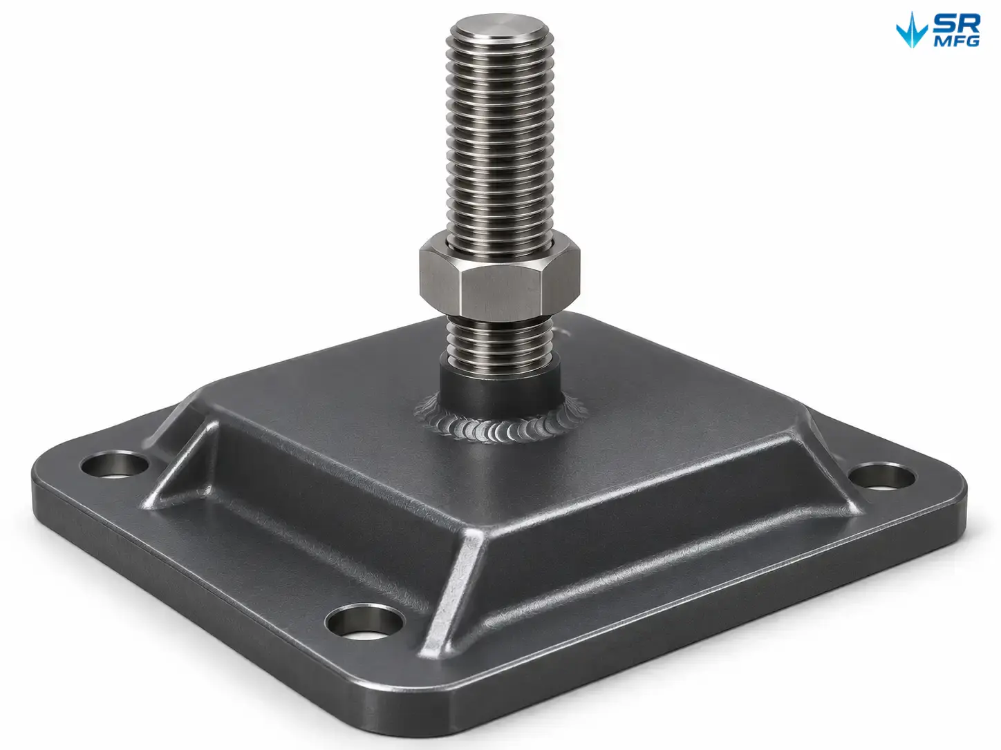
- Forming — flanges or raised edges added where stiffness is needed without extra thickness.
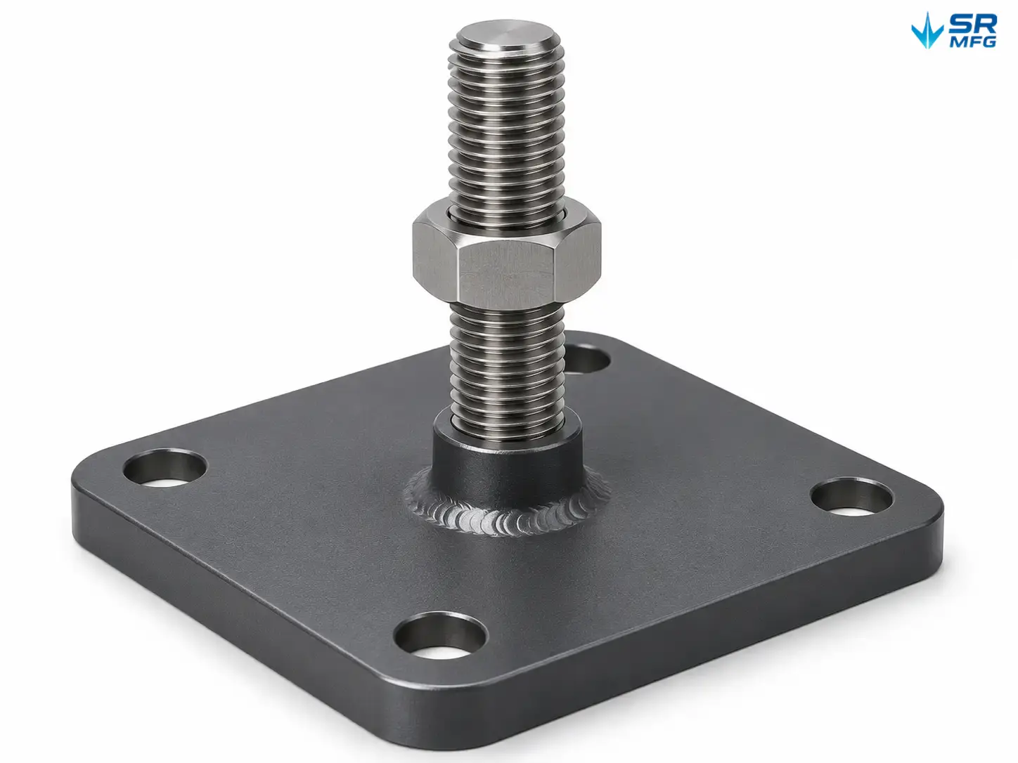
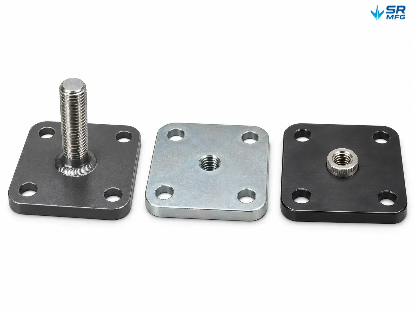
- Thread interface — stud welded to the plate, base tapped, or threaded insert installed. Each method changes load path and serviceability.
- Surface finishing — coating or conversion treatment applied after fabrication and inspection.
- Dimensional inspection — outline, hole positions, thread engagement, and flatness verified before packing.
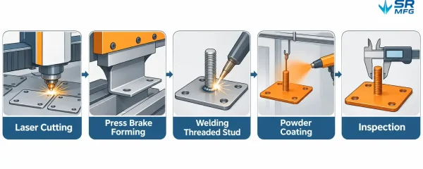
A horizontal process flow showing laser cutting, forming, thread attachment, surface finishing, and dimensional inspection steps for a leveling base plate.
Plate Thickness and Load Selection Logic
Load capacity is a function of plate thickness × outline size × reinforcement — not a single catalog number.
| Load Class | Typical Design Use | Plate Approach |
|---|---|---|
| Light Duty | Bench equipment, light frames, lab stands | Thinner plate, compact outline |
| Standard Duty | Machine tools, mid-weight assemblies | Mid-range thickness, optional flange |
| Heavy Duty | Presses, large pumps, heavy machine bases | Thicker plate, reinforced edge or gusset |
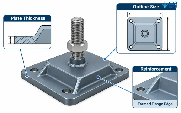
Diagram showing plate thickness, outline size, and reinforcement as three factors in leveling base plate load capacity
We size plates from your equipment weight and support point count. A four-point machine base does not need the same plate as a single-point pedestal. Provide the load per support point and we will confirm thickness and outline.
Thread Connection Types
| Connection | Structure | When to Use |
|---|---|---|
| Welded Stud | Stud welded to the plate face | Simple, high-strength connection; stud length easy to customize |
| Tapped Base | Hole tapped directly in the plate | Low-profile assemblies; serviceable with standard bolts |
| Threaded Insert | Press-in or weld-in insert | Thin plates that cannot hold full thread engagement |
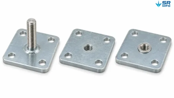
Three fabricated base plates side by side showing welded stud, tapped hole, and threaded insert connection types.
Metric and Inch thread sizes are available. Stud length is set by machine base thickness and required adjustment travel — we fabricate to your length, not to fixed catalog steps.
How the Leveling System Works
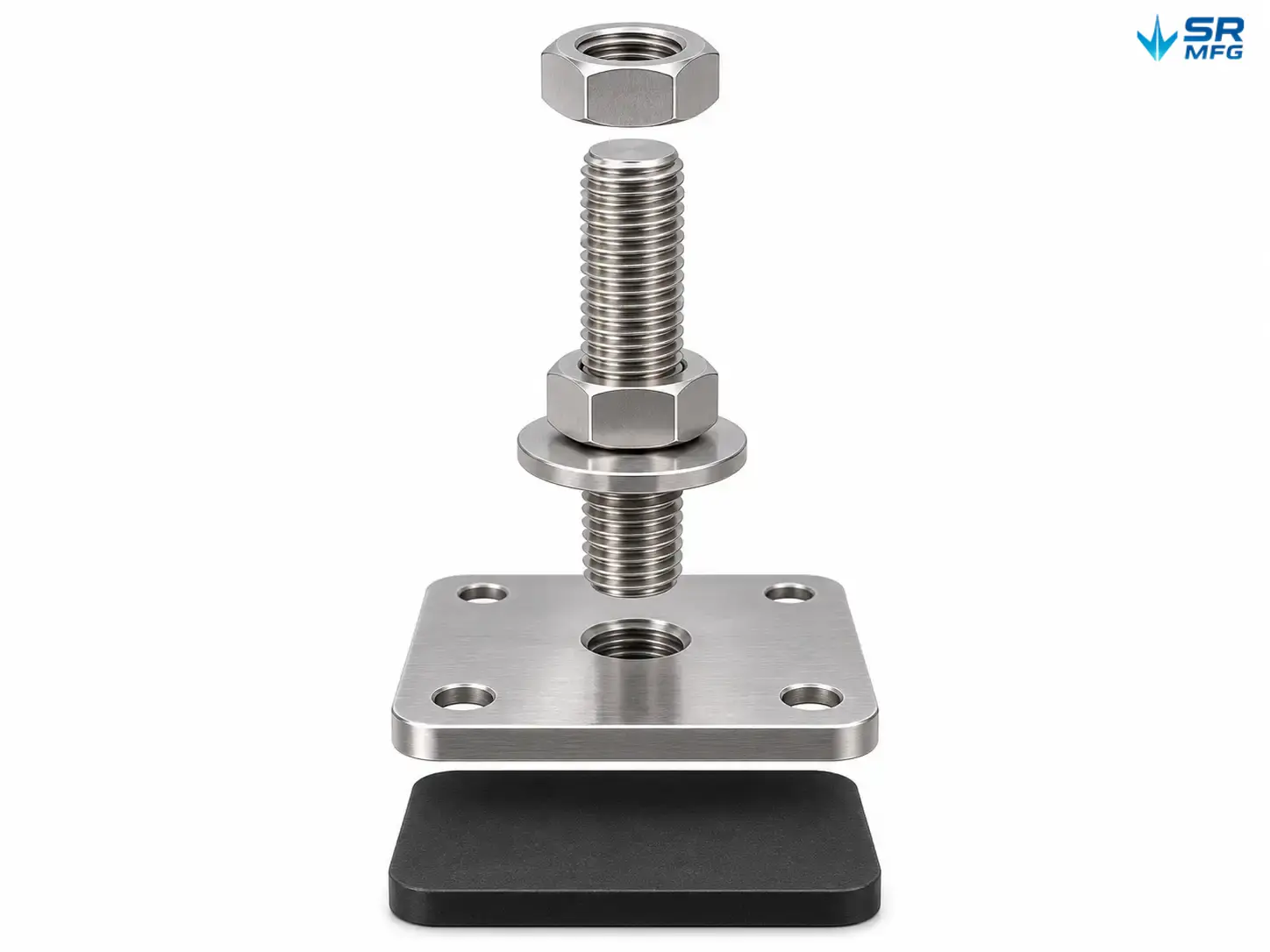
The plate stays fixed to the floor or the machine foot. The threaded stud turns in the plate (or into the insert), raising or lowering the load. A jam nut locks the setting.
- Adjustment travel depends on stud length. Extended studs are standard for thick machine bases.
- For large height corrections, shim under the base plate instead of running the stud at its travel limit.
- Anti-slip rubber or elastomer pads reduce creep on smooth floors and add vibration isolation.
This is a simple mechanism — which is exactly why plate quality and thread interface quality decide whether it holds under long-term load.
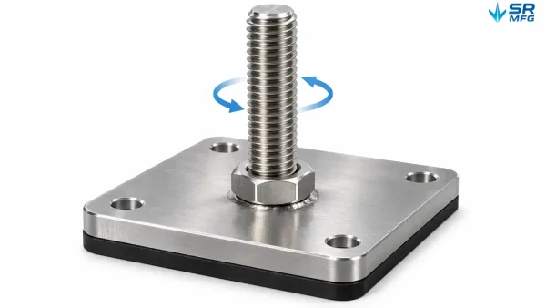
A close-up view of a leveling base plate showing the threaded stud, jam nut, and anti-slip pad as the adjustment and locking components.
Ordering and Fit Guidance
Confirm four points before ordering or requesting a quote:
- Equipment weight and number of support points → sets load class and plate thickness.
- Machine base footprint and bolt pattern → sets outline and mounting hole type.
- Thread interface and stud length → sets how the plate connects to the equipment.
- Operating environment → sets material and surface finish.
Quantity reference. Typical machine tools need 4 to 8 support points. Frames and conveyors vary with span. Order by total support points, not by machine count alone.
No drawing? Send the equipment model, a photo of the base, and rough dimensions. We will propose a plate layout and mark fit points before production.
Custom Fabrication to Your Requirements
Standard sizes cover common machine bases. Everything else is cut to your drawing.
| Custom Element | What We Can Do |
|---|---|
| Outline | Non-round, non-square, teardrop, or footprint-matched profiles |
| Thickness | Increased plate section for higher load or wider span |
| Hole Pattern | Matched to existing machine feet; slots for on-site adjustment |
| Thread | Custom stud length, dual threads, or insert type on one plate |
| Finish | Coating color, texture, and treatment selected for the environment |
| Marking | Part number, load mark, or orientation stamp |
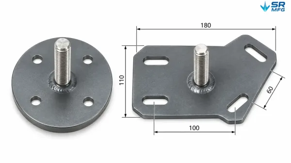
A side-by-side comparison of a standard round leveling plate and a custom outline plate cut to match a specific machine footprint.
Prototyping first is normal. For new machines or tight-clearance retrofits, we produce a sample plate for fit check before batch release. Production MOQ is confirmed per project — small batches are standard for equipment builders and maintenance teams.
Why Fabricated Plates Instead of Cast Mounts
| Factor | Fabricated Leveling Base Plate | Typical Cast Mount |
|---|---|---|
| Custom outline | Cut to your pattern | Fixed catalog shapes |
| Hole layout | Any pattern; slotted if needed | Fixed or limited |
| Load adjustment | Thickness and reinforcement chosen per load | Fixed by catalog size |
| Surface repair | Easy to recoat or replate | Cast finish hard to rework |
| Retrofit fit | Made to existing footprint | Often requires adapters |
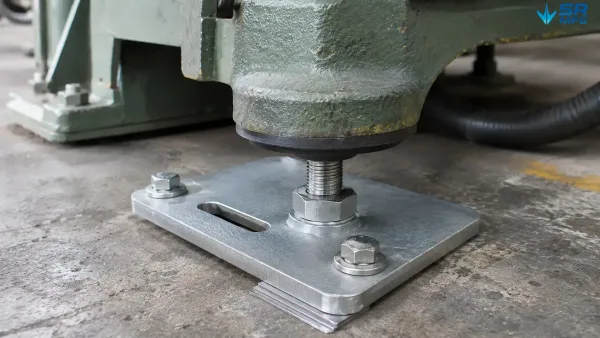
A fabricated leveling base plate supporting a machine foot on a rough industrial floor, with shims and a slotted hole allowing on-site adjustment.
Cast mounts still work for standard equipment on clean floors. When the footprint is non-standard, the floor is rough, or the load falls outside catalog ranges, a fabricated plate is the more reliable answer.
Inquiry CTA
Request a Quote for Custom Leveling Base Plates
Send your drawing, sample plate, or equipment details — weight per support point, base dimensions, thread type, surface finish, and quantity. We review the fit, confirm the load class and fabrication route, and return a quotation with lead time and prototype options. Repeat orders run from the approved drawing revision.