Custom sheet metal fabrication begins with a flat sheet of metal—a blank with a consistent thickness. Through processes such as laser cutting, bending, forming, welding, and surface finishing, that flat sheet is transformed into a finished component.
Unlike machined parts or injection-molded components, sheet metal parts are fundamentally constrained by how flat material deforms under tooling pressure.
A 3D model may look flawless in CAD, but it can still fail on the shop floor if the design does not account for:
- Bend radii
- Minimum flange lengths
- Feature-to-bend distances
- Material behavior
- Springback
- Press brake tooling and physical machine limitations
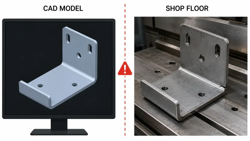
A side-by-side comparison showing how the same sheet metal bracket appears perfect in CAD software (left) versus the real-world manufactured part (right), which exhibits common issues like minor surface marks and a small bend-corner crack — demonstrating why CAD-accurate models can still fail during fabrication.
This sheet metal design guide is intended for engineers, mechanical designers, and product development teams. It explains the complete design logic required to convert a 3D CAD model into a manufacturable sheet metal drawing.
The primary objective is simple: identify manufacturing problems before prototyping begins—not after parts have already been produced.
Why CAD-Perfect Models Can Fail During Sheet Metal Fabrication
Why can a drawing look correct in CAD while the manufactured part still fails?
Most modern CAD platforms include dedicated sheet metal modeling tools. These tools can generate bends, flanges, reliefs, and flat patterns. However, the software cannot fully reproduce every real-world manufacturing condition.
A completed model may pass geometric checks in CAD, yet the physical part may still experience:
- Cracking along the bend
- Distorted holes or slots
- Inconsistent bend angles
- Insufficient tool clearance
- Assembly interference
- Incorrect final dimensions
The main reason is that sheet metal parts are not machined from solid blocks of material. They are manufactured from thin, flat sheets through a sequence that may include precision laser cutting, bending, forming, joining, and finishing operations.
Every feature in the design must survive these physical processes.
For example:
- If a hole is positioned too close to a bend line, it may stretch into an oval shape.
- If a flange is too short, the press brake tooling may not support it correctly.
- If the specified bend radius is too small for the material, the outside surface may crack.
- If the bend sequence is not considered, one flange may interfere with the tooling required to form another bend.
These are not unusual edge cases. They are among the most common reasons manufacturers return sheet metal drawings with design revision requests.
Understanding these issues before submitting an RFQ can save substantial time for both the design team and the sheet metal manufacturer.
Start With a Uniform Wall Thickness
The first requirement of any sheet metal design is that the entire part must maintain a single, uniform material thickness.
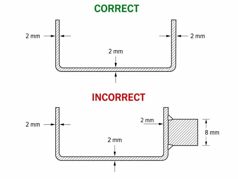
A cross-section engineering diagram comparing a correctly designed sheet metal part with uniform wall thickness (top, green) against an incorrectly designed part that includes a thick solid boss welded to a thin wall (bottom, red), illustrating why consistent material thickness is a fundamental requirement of sheet metal fabrication.
This is not merely a design preference. It is a physical manufacturing constraint.
The CAD model should be created using a thickness that corresponds to a commercially available sheet metal gauge or metric thickness.
If the model includes inconsistent wall thicknesses—for example, a thick solid boss integrated into a thin sheet—the part cannot normally be manufactured using standard sheet metal processes alone.
Additional operations, such as welding, machining, inserting a separate component, or redesigning the feature, may be required.
Common sheet metal thicknesses typically range from 0.5 mm to 6.0 mm.
Frequently used carbon steel and stainless steel thicknesses include:
- 1.0 mm
- 1.5 mm
- 2.0 mm
- 3.0 mm
Aluminum sheet metal is commonly used in thicknesses ranging from approximately 1.0 mm to 3.0 mm, although thinner and thicker material may also be available.
When selecting the material thickness, engineers should consider three primary factors:
- Load, stiffness, strength, and weight requirements
- Minimum bend radius and material formability
- Required forming force, standard stock sizes, material availability, and cost
The correct thickness should satisfy the functional requirements without unnecessarily increasing material cost, component weight, or forming difficulty.
Sheet Metal Bend Design Rules Every Engineer Should Know
Precision sheet metal bending is one of the most important processes in sheet metal fabrication. It transforms a flat profile into a three-dimensional component.
A large percentage of sheet metal design problems are directly related to bending, including:
- Incorrect bend radii
- Flanges that are too short
- Features located inside the bend deformation zone
- Insufficient springback compensation
- Tooling interference
- Poorly planned bend sequences
Addressing these issues during the CAD and drawing stages is essential for achieving consistent production results.
Determine the Minimum Bend Radius by Material
The minimum bend radius is the smallest internal radius that can be formed without causing unacceptable cracking on the outside surface of the bend.
It depends on several variables, including:
- Material type
- Material temper or condition
- Sheet thickness
- Grain direction
- Bend angle
- Forming method
- Tooling configuration
The following values can be used as general starting points.
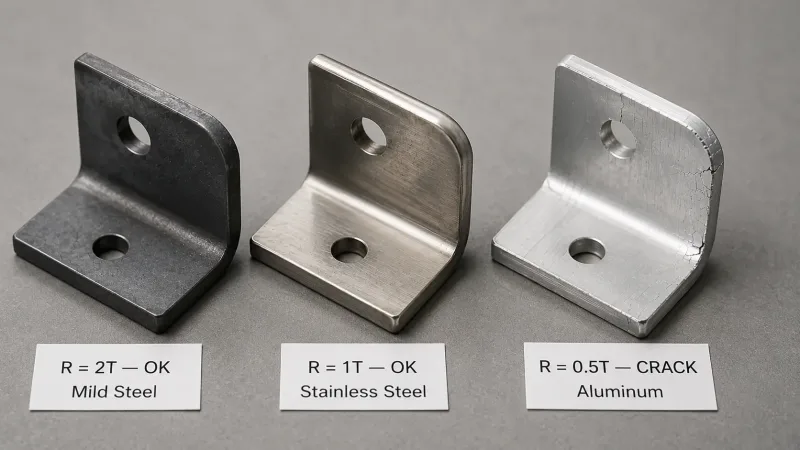
Three sheet metal L-brackets photographed side by side, each bent at a different radius. The left and center brackets show clean, smooth bends at safe radii, while the right bracket demonstrates what happens when the bend radius is too small for the material — visible cracking appears along the outside of the bend, illustrating why minimum bend radius rules matter.
| Material | Recommended Minimum Inside Bend Radius |
|---|---|
| Mild steel, including A36 and SPCC | 1 × T |
| Stainless steel, including 304 and 316 | 1 × T to 1.5 × T |
| Aluminum, including 5052 and 6061-O | 1 × T to 2 × T |
| High-strength steel, including DP600 and DP980 | 2 × T to 3 × T |
| Spring steel or hardened materials | 3 × T or greater |
T = material thickness
If the bend radius is smaller than the material can tolerate, the outside surface of the bend may crack.
Even when cracks are not visible to the naked eye, an excessively tight bend radius can:
- Reduce the strength of the bend
- Create localized stress concentrations
- Damage protective coatings
- Increase the risk of fatigue failure under repeated loading
For critical parts, the minimum bend radius should be confirmed with the material supplier and the selected sheet metal manufacturer.
Minimum Flange Length
The minimum flange length is the shortest straight section that can be reliably formed on one side of a bend.
It is determined primarily by the press brake tooling—not by the designer’s preferred geometry.
The achievable flange length depends on:
- Lower die V-opening
- Die shoulder radius
- Material thickness
- Bend angle
- Air bending, bottom bending, or coining method
- Punch and die geometry
For standard air bending, the V-opening for steel is often initially selected at approximately 6 to 8 times the material thickness.
With conventional press brake tooling, a flange length of approximately 6 × T can be used as a conservative preliminary design reference. However, the actual minimum should be calculated from the selected die geometry.
When a flange is shorter than approximately 3 × T, the tooling may not support the material securely. This can cause:
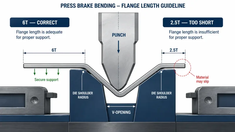
A cross-section technical illustration of press brake tooling showing how flange length affects bending accuracy. The left side shows an adequately long flange (6×T) supported securely by the V-die, while the right side shows a flange that is too short (2.5×T), where the material risks slipping because the die cannot grip it properly.
- Inconsistent bend angles
- Edge distortion
- Slippage during bending
- A combination of angle and dimensional errors
If a short flange is functionally necessary, a bend relief or local cutout may allow the flange to form without interfering with the tooling.
However, the relief will remain visible in the finished part. Therefore, short-flange designs should be reviewed with the manufacturer before the geometry is finalized.
K-Factor and Flat Pattern Accuracy
The K-factor represents the position of the neutral axis within the material thickness during bending.
When a sheet is bent:
- The inner surface is compressed.
- The outer surface is stretched.
- The neutral axis experiences neither significant compression nor tension.
The neutral axis is not normally located at the exact center of the sheet thickness. Its position depends on:
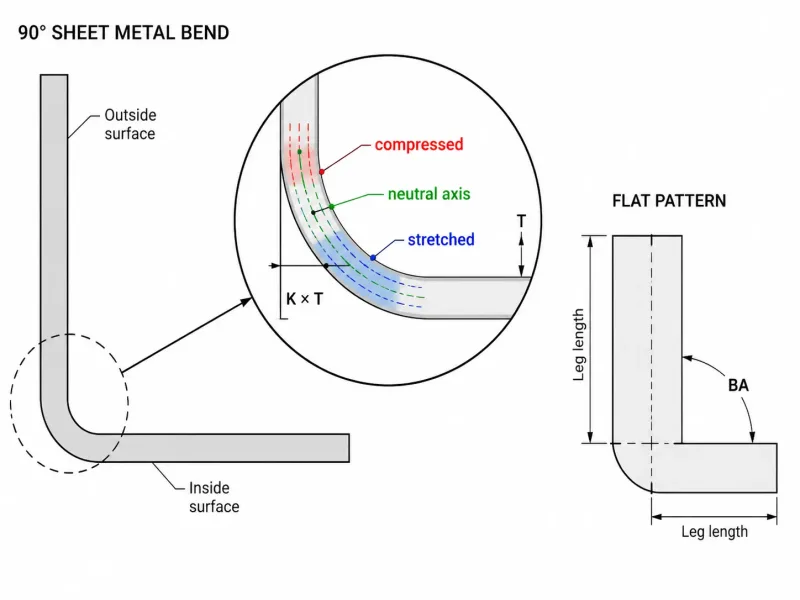
A cross-section of a 90-degree bend illustrating how the inner surface is compressed (red), the outer surface is stretched (blue), and the neutral axis (green dashed line) sits between them — offset from the center. The K-factor defines this neutral axis position, which directly determines the bend allowance used to calculate the flat pattern.
- Material type
- Material condition
- Inside bend radius
- Sheet thickness
- Forming process
- Tooling configuration
A common initial estimate for the K-factor is between 0.33 and 0.40, although the actual value may vary.
| Material | Typical K-Factor Range |
|---|---|
| Mild steel | 0.35–0.40 |
| Stainless steel | 0.35–0.45 |
| Soft-temper aluminum | 0.33–0.38 |
| Hard-temper aluminum | 0.38–0.42 |
The K-factor directly affects the bend allowance, which represents the amount of material consumed by the bend in the flat pattern.
An incorrect K-factor produces an incorrect flat pattern.
After bending, the finished part may therefore be:
- Too long
- Too short
- Incorrectly positioned relative to holes or cutouts
- Outside the required overall dimensions
For components with multiple bends, small errors can accumulate after every operation. By the final bend, the location of a critical mounting feature may be significantly incorrect.
Most sheet metal CAD programs can automatically calculate bend allowances after the user enters a K-factor. However, engineers should verify the bend data instead of relying blindly on the software’s default values.
For repeat production, the most reliable values are often derived from the manufacturer’s proven bend tables, tooling records, and test coupons.
Springback Compensation
Springback is the tendency of sheet metal to partially return toward its original flat condition after the bending force is removed.
Every metal experiences some degree of springback. It is a natural result of elastic material behavior, not a manufacturing defect.
Stainless steel and high-strength steel generally exhibit more springback than mild steel or soft-temper aluminum.
For example:
- A 90-degree bend in 304 stainless steel may spring back approximately 2° to 4°.
- A similar bend in mild steel may spring back approximately 1° to 2°.
-
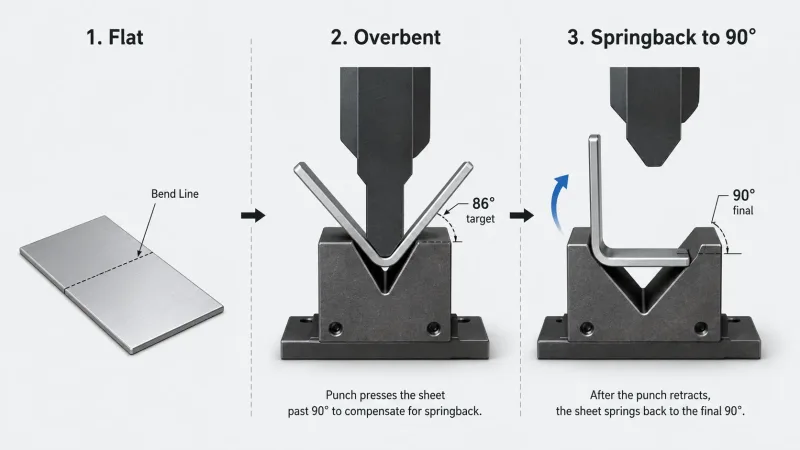
A three-stage sequence showing how springback compensation works: (1) the flat sheet is positioned, (2) the press brake overbends the sheet to approximately 86 degrees, and (3) after the punch retracts, the material’s natural elastic recovery springs it back to the target 90-degree angle — illustrating why manufacturers must deliberately overbend to achieve the correct final dimension.
Manufacturers compensate for springback by overbending the part. The material is formed beyond the target angle so that it relaxes into the required final position after the tooling pressure is removed.
This compensation is normally controlled during press brake programming. However, engineers should understand springback for two important reasons:
- Tight angular tolerances may require precision tooling, bottom bending, coining, or additional inspection, increasing manufacturing cost.
- Parts with multiple bends may accumulate dimensional errors if bend sequence and springback are not adequately controlled.
Material batches, rolling direction, tooling wear, and forming conditions can also affect the amount of springback.
Feature Placement: Keep Holes, Slots, and Cutouts Away From Bend Zones
Holes, slots, louvers, and other cut features are often placed close to bend lines because the arrangement appears logical from an assembly perspective.
However, the area surrounding a bend line is a deformation zone.
During bending, the material in this region is:
- Stretched
- Compressed
- Shifted
- Rotated relative to the flat pattern
Any feature located inside this zone may become distorted.
The following distances can be used as initial sheet metal design guidelines.
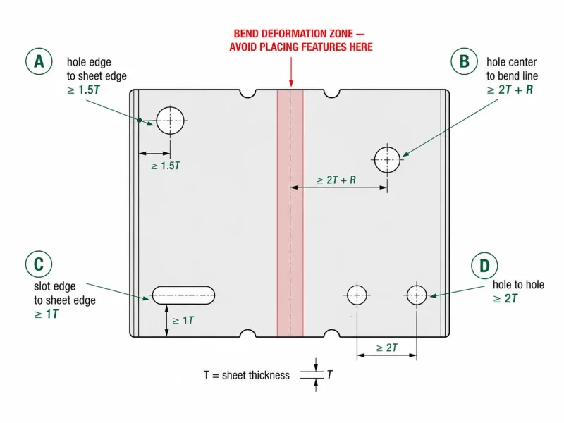
A top-view technical diagram of a flat sheet metal part with a bend line running through the center. Four callout examples illustrate the critical minimum distances: hole-to-edge, hole-to-bend-line, slot-to-edge, and hole-to-hole. The red-shaded zone along the bend line marks the deformation area where features should not be placed, as they risk becoming distorted during bending.
| Feature Relationship | Recommended Minimum Distance |
|---|---|
| Hole edge to sheet edge | ≥ 1.5 × T |
| Hole center to bend line | ≥ 2 × T + bend radius |
| Slot edge to sheet edge | ≥ 1 × T, provided slot width ≥ T |
| Edge-to-edge distance between two holes | ≥ 2 × T or ≥ 1 mm, whichever is greater |
| Feature-to-feature distance on the same face | ≥ 2 × T |
For ordinary small holes, a practical initial design rule is:
D ≥ 2 × T + R
For larger holes or elongated slots, a more conservative rule is:
D ≥ 2.5 × T + R
Where:
- D is the distance from the nearest edge of the feature to the bend tangent line
- T is the material thickness
- R is the inside bend radius
It is important to define D correctly. It is not the distance from the hole center to the nominal bend centerline.
If the required distance cannot be maintained, the manufacturing sequence should be discussed with the supplier. In some cases, bending first and machining, drilling, or punching the feature afterward may produce a more reliable result.
Tolerance Strategy: Control What Matters and Release What Does Not
Every dimension on a drawing has either an explicit tolerance or an implied general tolerance, both of which should align with the applicable sheet metal inspection standards.
The primary challenge in sheet metal manufacturing is not simply whether a tight tolerance can be achieved. The real challenge is identifying which tolerances are functionally necessary and which provide no meaningful benefit.
Typical achievable tolerances for standard sheet metal fabrication may include:
| Dimension Type | General Tolerance | Tight Tolerance With Additional Cost |
|---|---|---|
| Laser-cut profile dimension | ±0.50 mm | ±0.15 mm |
| Hole position | ±0.25 mm | ±0.10 mm |
| Hole diameter | ±0.10 mm | ±0.05 mm |
| Bend angle | ±1° | ±0.5° |
| Bend-to-hole distance | ±0.50 mm | ±0.25 mm |
These values are general references only. Actual capability depends on:
- Material
- Thickness
- Part size
- Feature geometry
- Number of bends
- Machine condition
- Tooling
- Inspection method
- Production volume
A practical design principle is to apply specific tolerances only to dimensions that directly affect fit, assembly, sealing, alignment, or function. All other dimensions should be governed by an appropriate general tolerance.
For example, if a sheet metal bracket is mounted to a frame using M6 bolts, the following dimensions may be critical:
- Bolt-hole locations
- Hole spacing
- Overall mounting width
- Interface height
- Datum relationships
By contrast, the exact position of a nonfunctional outer edge or the angle of a non-mating flange may not require a tolerance of ±0.10 mm.
Over-tolerancing is one of the most common problems found in sheet metal drawings.
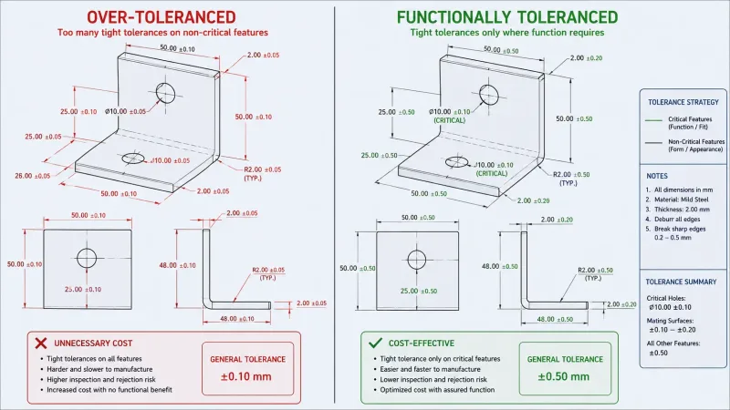
Two versions of the same sheet metal bracket drawing side by side. The left drawing is overloaded with tight tolerances (±0.10 mm) on every dimension — including edges that don’t affect function — leading to unnecessary cost. The right drawing applies tight tolerances only to critical mounting holes and mating surfaces, while using practical general tolerances elsewhere, demonstrating a cost-effective tolerance strategy.
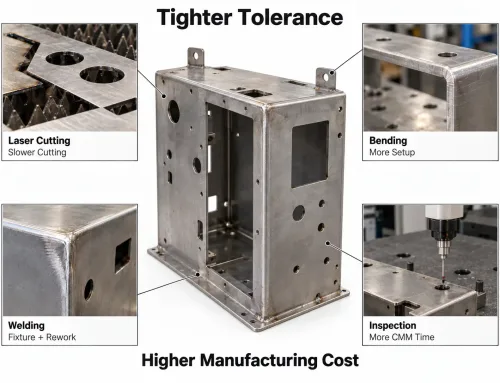
Excessively tight tolerances do not automatically improve the part. Instead, they may:
- Increase the quoted price
- Extend lead times
- Require additional inspection
- Reduce manufacturing yield
- Force the manufacturer to use a more expensive production method
- Require machining after bending
The tolerance strategy should reflect the functional requirements of the assembly—not an arbitrary desire for maximum precision.
Material Selection and Surface Finishing: Decisions That Affect the Final Part
Choosing the Right Sheet Metal Material
Material selection requires a balance between:
- Mechanical strength
- Stiffness
- Formability
- Corrosion resistance
- Weight
- Appearance
- Availability
- Cost
The three most commonly used sheet metal material options are mild steel, stainless steel, and aluminum.
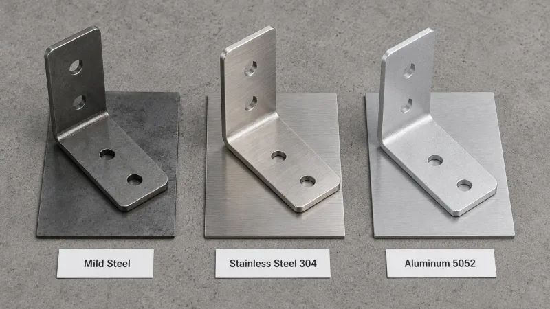
Three identical L-bracket samples photographed side by side, each fabricated from a different common sheet metal material — mild steel, stainless steel 304, and aluminum 5052. The brackets share the same geometry but differ visibly in surface tone and texture, giving readers a direct visual reference for how material choice affects the appearance and finish of the final part.
| Material | Advantages | Limitations | Common Thickness Range |
|---|---|---|---|
| Mild steel, including A36, SPCC, and DC01 | Low cost, good formability, widely available | Susceptible to corrosion without a protective finish | 0.5–6.0 mm |
| Stainless steel, including 304 and 316 | Strong corrosion resistance and clean appearance | Higher cost, greater springback, more difficult to bend | 0.5–4.0 mm |
| Aluminum, including 5052 and 6061 | Lightweight, corrosion resistant, easy to cut | Lower stiffness than steel; hard tempers may have greater springback and cracking risk | 0.5–6.0 mm |
One factor frequently overlooked by designers is material grain direction.
Sheet and coil materials develop a rolling direction during production. Bending perpendicular to the grain generally produces more consistent results and a lower risk of cracking than bending parallel to the grain.
This consideration is especially important for:
- Hard-temper aluminum
- High-strength steel
- Small bend radii
- Critical structural parts
- Components subjected to fatigue loading
For critical applications, the required grain direction should be clearly specified on the drawing or flat pattern.
Surface Finishing Changes Part Dimensions
Sheet metal finishing processes are often treated as the final step after the design has been completed. However, these treatments can directly affect assembly dimensions.
Most coatings add measurable thickness to the part.
| Surface Finish | Approximate Thickness Added Per Side |
|---|---|
| Powder coating | 0.06–0.12 mm |
| Wet paint | 0.02–0.05 mm |
| Zinc electroplating | 0.005–0.015 mm |
| Aluminum anodizing | 0.005–0.08 mm |
| Stainless steel passivation | Negligible dimensional change |
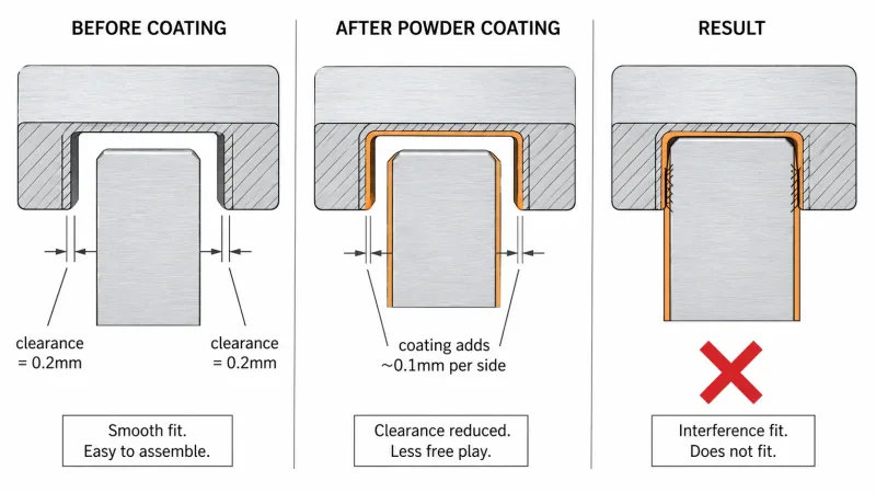
A three-panel cutaway diagram illustrating how surface coating affects sheet metal assembly fit. Before coating, the tab fits into the slot with comfortable clearance. After powder coating adds approximately 0.1 mm per side, the clearance is consumed and the assembly becomes an interference fit that no longer goes together — showing why coating thickness must be accounted for during the design stage.
Coating thickness can affect:
- Tab-and-slot assemblies
- Hinges
- Sliding components
- Threaded holes
- Installation and fit of sheet metal parts with PEM nuts
- Press-fit features
- Gasket compression
- Enclosure door gaps
- Mating surfaces
The preferred approach is to specify the required surface finish during the design stage and include coating thickness in all relevant fit and clearance calculations.
Areas that must remain electrically conductive, dimensionally controlled, or free from coating should also be clearly identified on the manufacturing drawing.
Prototype and Production Design Require Different Priorities
A sheet metal part designed for a prototype quantity of 10 pieces may look identical in CAD to the same part intended for a production volume of 5,000 pieces.
However, the manufacturing process and cost structure can be completely different.
| Design Consideration | Prototype and Low-Volume Production | Stable High-Volume Production |
|---|---|---|
| Cutting method | Laser cutting offers flexibility, fast lead times, and no dedicated tooling investment | Stamping or progressive dies reduce unit cost but require greater tooling investment |
| Bending | Standard press brake tools and general-purpose tooling | Dedicated or custom tooling may improve consistency and production efficiency |
| Tolerances | May be relaxed when the primary objective is functional validation | Must be controlled within a repeatable production capability |
| Surface finish | May be simplified or omitted for assembly-only prototypes | Must match the final product specification |
| Nesting and material utilization | Less critical for small quantities | Essential because optimized nesting can significantly reduce material waste and cost |
| Design changes | Relatively easy between prototype iterations | May require tooling modifications, increasing cost and lead time |
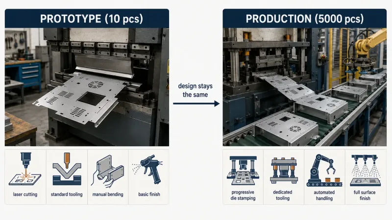
A two-column comparison infographic showing how the same sheet metal enclosure panel is manufactured differently at prototype volume (10 pieces — laser cut, standard press brake, manual handling) versus production volume (5,000 pieces — progressive stamping die, dedicated tooling, automated handling), with a connecting arrow emphasizing that the part design remains unchanged while only the manufacturing process scales.
The best approach is to design for the expected production process from the beginning.
During rapid sheet metal prototyping, the manufacturer can select flexible processes such as laser cutting and standard press brake bending. As production volume increases, the part can transition to dedicated tooling, stamping, or automated manufacturing with little or no design modification.
This strategy helps prevent expensive redesigns after the product has already entered production.
How SR-MFG Supports Your Sheet Metal Design Process
SR-MFG provides end-to-end custom sheet metal fabrication services, including:
- Laser cutting
- Press brake bending
- Welding
- Hardware insertion
- PEM fastener and self-clinching nut installation
- Tapping
- Powder coating
- Surface finishing
- Mechanical assembly
Before quotation, our engineering team performs a sheet metal DFM review of incoming 3D CAD models, including:
- Bend radius compliance
- Minimum flange length
- Feature placement
- Tooling accessibility
- Tolerance feasibility
- Material suitability
- Surface finish requirements
- Potential assembly risks
Whether you are ordering an initial prototype for fit and assembly testing or preparing a production order for thousands of parts, we work with you to ensure that the design is manufacturable and that the quotation reflects the most efficient production method.
Submit your STEP file, material specification, surface finish requirements, critical tolerances, and required quantity to receive a fast and detailed sheet metal fabrication quote.