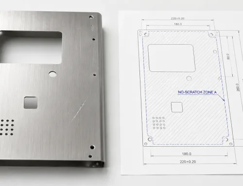
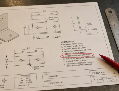
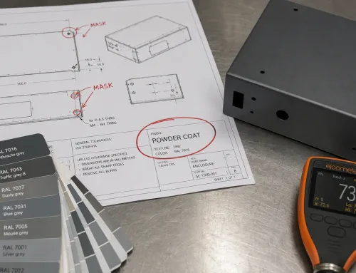
What does your sheet metal supplier need to see on your drawings? What happens when that information is missing?
When a custom sheet metal fabrication supplier receives your drawing package, it does not immediately begin laser cutting or bending. The first step is to assess whether the files are complete.
A complete package containing a 3D CAD model, a 2D drawing, and the correct file formats enables faster quoting and more accurate manufacturing. Incomplete files can delay quotations and, in some cases, result in scrapped parts.
What Makes Sheet Metal Drawings Different?
Sheet metal parts are not machined from solid blocks. They are formed from flat metal sheets through multiple fabrication processes. This difference affects how sheet metal drawings are created and interpreted.
A standard CNC machining drawing mainly focuses on the dimensional tolerances and surface finish of a solid part. Sheet metal drawings must communicate additional manufacturing information.
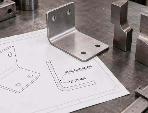
In addition to finished dimensions, sheet metal fabrication drawings should include a flat pattern showing the pre-bend shape, bend lines with direction indicators, bend angles, and bend radii. In some cases, the material grain direction must also be specified.
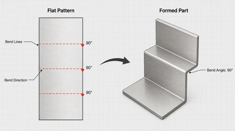
This diagram shows how a flat metal sheet (left) with bend lines transforms into a finished 3D bracket (right) after bending. The bend lines, bend direction arrows, and bend angles are labeled on the flat pattern — the key details that distinguish sheet metal drawings from standard machining drawings.
These details are not normally found on drawings for conventional prismatic machined parts, and missing them is a common cause of manufacturing delays.
The Roles of 2D Drawings, 3D Files, and PDFs
Submitting only one file type—whether a 2D drawing or a 3D model—is generally not enough for sheet metal fabrication. Each file serves a different purpose in the manufacturing workflow. The most efficient approach is to use all three together.
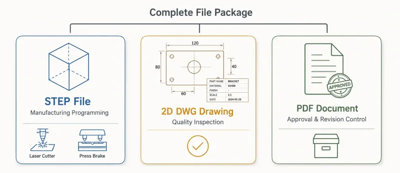
This diagram illustrates the distinct roles of three file types in sheet metal fabrication: the 3D STEP file drives manufacturing programming (laser cutting, bending), the 2D DWG drawing defines quality inspection requirements, and the PDF serves as the approval and revision reference document. Using all three together ensures the fastest quoting and most accurate production.
Purpose of 3D CAD Files
A 3D model, usually supplied to the sheet metal fabricator in STEP format, is the basis of modern sheet metal programming.
The fabricator can use the 3D file to begin:
- Generating laser-cutting paths
- Calculating flat patterns through automatic unfolding
- Optimizing material utilization through nesting
- Generating CNC press brake bending programs
Without a 3D file, the fabricator may need to reconstruct the geometry from the 2D drawing, which is time-consuming and prone to error.
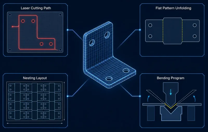
A 3D STEP file enables four key manufacturing steps: generating laser-cutting paths, automatically unfolding the part into a flat pattern, optimizing material utilization through nesting, and generating bending programs. Without this file, the fabricator must manually reconstruct the geometry from 2D drawings — a slower and error-prone process.
Purpose of 2D Drawings
Although the manufacturing process is driven by the 3D file, the 2D drawing defines the acceptance requirements.
The following information should be shown on the 2D drawing:
- Critical dimensions
- Geometric tolerances
- Surface finish specifications
- Hardware callouts
- Assembly datums
Quality inspectors rely on these drawings to verify the finished part. The 2D drawing therefore acts as the binding document between what was ordered and what was delivered.
A 3D model alone cannot fully indicate which dimensions are critical to assembly and which are for reference only.
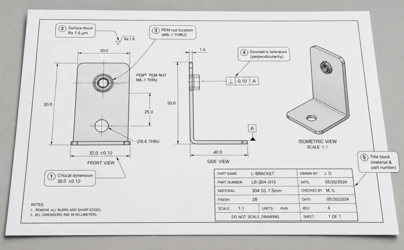
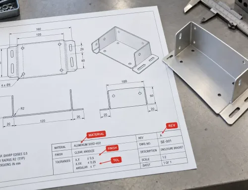
A well-prepared 2D sheet metal drawing should include clearly labeled critical dimensions with tolerances, surface finish specifications, hardware installation callouts, assembly datums, and a complete title block. This annotated example shows each essential element that quality inspectors rely on to verify the finished part.
Purpose of PDF Files
PDF files are not used for manufacturing programming. Their purpose is document management, revision control, approval tracking, and archiving.
Although a design may go through several revisions, only the signed and approved PDF is used as the production reference.
Many sheet metal fabricators accept PDFs as supporting documents, but they normally will not quote or manufacture a part using only a PDF when no 3D model or 2D drawing is available.
Define File Priority
When submitting files, clearly identify which document controls production and inspection.
A common approach is:
- A revision-controlled 2D PDF defines tolerances, materials, surface finishes, and inspection requirements
- The STEP model defines the nominal 3D geometry
- The DXF communicates the approved 2D cutting profile
- Flat patterns generated by the fabricator are supplier process files
If the 2D drawing, 3D model, and DXF conflict, the discrepancy should be confirmed in writing before quotation or production. The machine operator should not be expected to choose which file to follow.
Choosing the Correct File Formats
The file formats you submit determine how efficiently the sheet metal fabricator can process your design.
The table below summarizes the most common formats used in sheet metal fabrication.
| Format | File Type | Main Use | Notes |
|---|---|---|---|
| STEP (.stp, .step) | 3D | Manufacturing programming, flat-pattern calculation, nesting optimization | Universal 3D exchange format; preferred by most fabricators |
| DXF (.dxf) | 2D | Laser-cutting profiles and flat-pattern outlines | Suitable for simple flat parts or 2D cutting profiles |
| DWG (.dwg) | 2D | Dimensioned drawings and tolerance callouts | Native AutoCAD format; widely supported |
| PDF (.pdf) | 2D reference | Approval records and revision reference | Not used for manufacturing programming |
For many sheet metal projects, the recommended combination is a STEP file for the 3D geometry and a dimensioned PDF or DWG for the 2D specifications.
For a simple flat profile that requires no bending, a single DXF file may be sufficient.
Information Every Sheet Metal Drawing Must Include
A complete sheet metal drawing must tell the fabricator four things:
- What shape must be cut?
- How must it be bent?
- What material must be used?
- How must the finished part be verified?
Each requirement must be communicated through specific information on the drawing.
Views and Layout
A sheet metal drawing should include at least:
- Front view
- Side view
- Isometric view
- Flat pattern
The front and side views show the formed geometry.
The isometric view provides a visual reference.
The flat pattern shows the shape before bending.
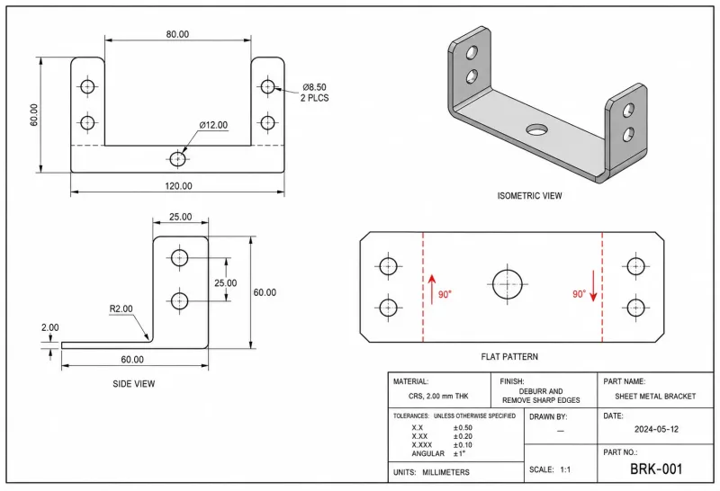
A complete sheet metal drawing should include at least four views: a front view and side view showing the formed geometry, an isometric view for visual reference, and a flat pattern showing the part’s shape before bending. The isometric view is especially important for complex parts where multiple bends interact.
The isometric view is particularly important for complex parts because it resolves details that orthographic projections may not clearly communicate, especially when several bends interact.
Required Title Block Information
The title block is one of the first areas reviewed by the fabricator. It should include:
- Material grade and sheet thickness: 304 stainless steel, 1.5 mm
- Surface finish: powder coating, RAL 7035, 60–80 μm
- Required quantity
- Part number and revision
- Applicable tolerance standard: ISO 2768-mK
Dimensions and Tolerances
Dimensions on sheet metal drawings should follow standard engineering drawing practices:
- Clearly identify reference dimensions
- Apply explicit tolerances to critical features
- Avoid redundant dimensions
When tolerances are not specified, the fabricator may apply general tolerances based on the material and manufacturing process.
Common reference values include:
- Laser cutting: ±0.1 mm
- Each bend: ±0.3 mm
- Hole diameter: ±0.05 mm
- Overall length: ±0.2 mm per metre
These general values do not replace explicit tolerances on critical features.
Specifying Surface Finishes and Secondary Operations
Sheet metal parts often require processes beyond cutting and bending.
Welding, hardware installation, tapping, and sheet metal surface finishing are common secondary operations. Each must be clearly specified on the drawing to prevent manufacturing errors.
Welding
When a part requires welding, the drawing should identify the weld location and weld type.
It should state whether the part requires:
- Spot welding
- Continuous full welding
- TIG welding
- Specific appearance or dimensional quality requirements
For assemblies containing multiple parts, a separate assembly drawing should be provided to show weld locations.
Hardware Installation
Self-clinching fasteners, such as PEM studs, nuts, and standoffs, are widely used in sheet metal assemblies.
The drawing should specify:
- Fastener type
- Standard part number
- Installation location
- Installation direction
- Protruding or flush requirements
Calling out the PEM or equivalent standard part number directly on the drawing eliminates guesswork and prevents incorrect installation.
Tapping and Threads
Thread specifications should include:
- Thread size and pitch
- Thread depth
- Location on the part
For example: M3 × 0.5.
Blind threaded holes require particular attention. The sheet metal fabricator must know the minimum thread engagement depth to select the correct tap and prevent it from bottoming out.
Surface Finishing
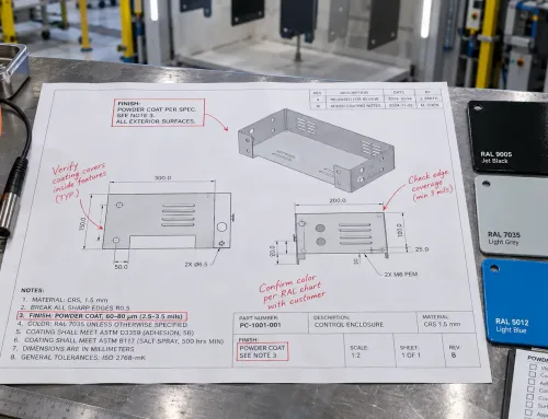
Surface finish callouts must be specific. Simply writing “paint” or “coating” is not sufficient.
A complete specification should include:
- Coating thickness range, such as 60–80 μm
- Surfaces to be coated
- Masking requirements
For anodizing, specify:
- Type II: decorative
- Type III: hard anodizing
- Colour and thickness class
Common Drawing Errors That Delay Quotations
The following issues are frequently identified during sheet metal RFQ reviews.
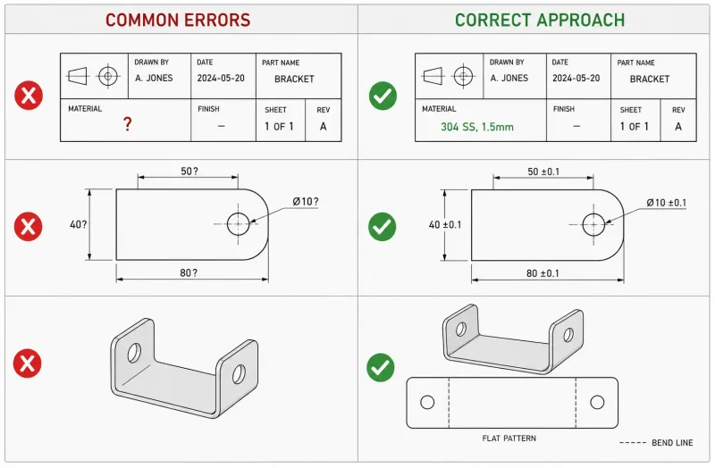
Six common drawing errors that delay sheet metal quotations: missing material specification, missing critical tolerances, no flat pattern or bend callouts, vague surface finish descriptions, unspecified bend direction, and missing assembly files for multi-part projects. Each error is shown alongside its correct version for quick reference.
| Common Problem | Effect on the Quotation |
|---|---|
| Material grade or sheet thickness not specified | Material cost and stock availability cannot be confirmed |
| Critical dimensions have no tolerances | The engineering team must request clarification or make assumptions that may not reflect the design intent |
| No flat pattern or bend callouts | The fabricator must regenerate the flat pattern from the 3D model and confirm the bending details, adding 1–3 days |
| Surface finish described with only one word, such as “paint” | Coating type, colour, and thickness must be confirmed before quotation |
| Bend direction not specified | There is a risk of bending in the wrong direction, requiring the engineering team to infer and confirm the correct orientation |
| No assembly file for a multi-part project | Part relationships, fit requirements, and assembly sequence cannot be determined |
Most of these issues can be avoided with a few minutes of checking before submitting the RFQ.
How File Requirements Change from Prototypes to Production
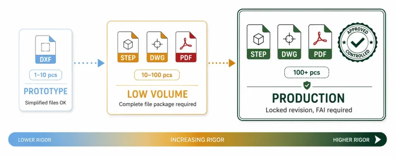
File requirements become more rigorous as projects move from prototype (1–10 pieces, simplified files accepted) through low-volume (10–100 pieces, complete file package required) to production (100+ pieces, drawings serve as formal manufacturing control documents with locked revisions).
Prototype Stage: Typically 1–10 Pieces
At the prototype stage, the fabricator may accept simplified files, such as a basic dimensioned 2D DXF or a STEP file accompanied by brief written instructions.
Speed is the priority, and both parties understand that some details may be confirmed verbally.
However, this flexibility introduces risk. Without formal documentation, the finished part may differ from the designer’s intent.
Low-Volume Stage: 10–100 Pieces
At this stage, a complete file package must be submitted.
It should include:
- A 3D model
- A fully dimensioned 2D drawing
- Tolerances
- Material specifications
- Surface finish requirements
Verbal confirmations should now be replaced by written drawing callouts.
Production Stage: More Than 100 Pieces
At this stage, drawings should be used as manufacturing control documents.
They should include:
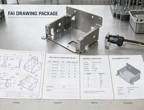
- Sheet metal First Article Inspection requirements
- Packaging specifications
- A locked revision number
Any design change should be incorporated into the drawings through a formal revision process before the next production run.
Pre-Submission Checklist
Before sending files to a sheet metal fabricator, confirm that the following information is complete.
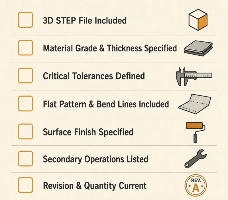
Before sending files to a sheet metal fabricator, verify that all seven checklist items are complete: 3D STEP file included, material and thickness specified, critical tolerances defined, flat pattern with bend details included, surface finish fully specified, secondary operations listed, and revision and quantity confirmed as current.
| Checklist Item | What to Confirm |
|---|---|
| 3D file included | STEP or STP format; individual part file rather than an assembly, unless an assembly quotation is required |
| Material specified | Alloy grade and sheet thickness shown in the title block or BOM, such as AA 5052-H32 aluminum, 2.0 mm |
| Critical tolerances defined | Assembly dimensions, hole positions, mating surfaces, and other critical features have explicit tolerances |
| Flat pattern included | Bend lines, bend directions, and bend angles are shown for all formed features |
| Surface finish specified | Colour, coating type, film thickness, and coated surfaces are defined |
| Secondary operations specified | Weld locations, hardware types, thread specifications, and special processes are listed |
| Revision and quantity are current | The title block shows the latest revision and correct order quantity |
This checklist does not replace the fabricator’s engineering review, but it helps ensure that your files are complete enough for the review to begin without delay.
How SR-MFG Supports Your RFQ Process
The SR-MFG engineering team reviews every drawing package before quotation to check its completeness and manufacturability.
The review covers:
- Material and sheet thickness verification
- Flat-pattern accuracy
- Bending feasibility
- Tolerance analysis
- Identification of all secondary operations
If information is missing, the team contacts you about the specific issue rather than returning the entire package. This reduces repeated communication, shortens engineering confirmation time, and helps keep the project on schedule.
To submit a sheet metal RFQ, send your 2D drawings, 3D CAD files, material and surface finish specifications, required quantity, and any special requirements to the SR-MFG engineering team.