Your sheet metal part passes every DFM check — correct bend radius, standard hole sizes, proper material thickness. The flat pattern nests efficiently, the tolerances are achievable, and the quote comes back without red flags.
Then production starts, and the assembly technician calls up:
“I can’t get a wrench onto these bolts.”
Tool access is one of the most overlooked aspects of sheet metal design. It rarely shows up in automated DFM analysis because software checks geometry — hole diameters, edge distances, bend clearances — but it does not simulate whether a human hand holding a real tool can physically reach a fastener inside a formed enclosure.
By the time the problem surfaces on the shop floor, the fix usually means re-cutting or re-bending the part.
This guide explains how to design sheet metal parts that account for tool clearance from the start, covering the tools involved, the fastener choices that affect access, the role of assembly sequence, and the differences between prototype and production environments.
Why Tool Access Gets Missed in Sheet Metal Design
The root cause is simple: CAD environments do not have tool models.
When an engineer places a bolt in a 3D assembly, the software confirms that the bolt fits through the hole and that the head clears adjacent features.
What it does not check is whether a socket wrench — which is wider than the bolt head and needs room to rotate — can fit in the same space.
The bolt is geometrically correct but practically inaccessible.
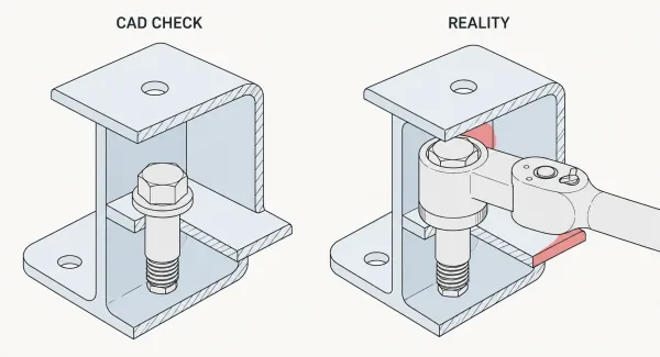
A side-by-side technical illustration comparing how a bolt passes CAD clearance checks (left) versus how a socket wrench collides with surrounding geometry in the real assembly (right), with red zones highlighting interference.
This gap exists because most sheet metal DFM guidelines focus on manufacturability — can the part be laser-cut, bent, and finished — rather than assemblability.
The design review process catches problems like impossible bend sequences or features too close to an edge, but it rarely asks:
“How does the technician actually tighten this fastener?”
The result is a part that is easy to fabricate and difficult to assemble.
Common Tools and the Clearance They Demand
Different assembly operations require different tools, and each tool has specific space requirements.
The table below summarizes the most common tools used in sheet metal assembly and the minimum clearance they need to operate.
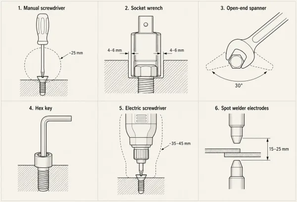
A cross-section diagram illustrating the minimum clearance envelopes required by six common assembly tools — screwdriver, socket wrench, spanner, hex key, electric screwdriver, and spot welder electrodes — with key dimensions annotated.
| Tool | Minimum Clearance Requirement | Notes |
|---|---|---|
| Manual screwdriver | Straight-line access path, ~25 mm diameter | Needs room for wrist rotation |
| Socket wrench | Counterbore diameter should be 4–6 mm larger than bolt head | Impact wrenches need even more space |
| Open-end spanner | 30° minimum swing angle per stroke | At 15° or less, tightening one bolt can take 10+ minutes |
| Hex key (Allen key) | Vertical access above the fastener | Works in tight lateral spaces where spanners cannot swing |
| Electric/pneumatic screwdriver | ~35–45 mm diameter clearance | Larger body than manual driver; needs straighter approach angle |
| Resistance spot welder electrodes | Depends on electrode tip geometry, typically 15–25 mm access gap | Electrodes must reach both sides of the joint simultaneously |
| Adhesive applicator nozzle | ~10–15 mm access width | Must maintain consistent bead path; cramped space causes uneven application |
A common mistake is designing clearance only for the manual tool used during prototyping.
On a production line, the technician may use an electric screwdriver or pneumatic wrench that is significantly larger.
If the design does not account for this, the assembly works fine in small quantities but becomes a bottleneck at volume.
Fastener Access: Matching Hardware to Available Space
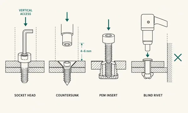
Cross-section comparison of four fastener types — socket head cap screw, countersunk screw, PEM insert, and blind rivet — showing the tool approach direction and access envelope for each.
The fastener you choose directly determines the tool access you need.
When space is constrained, changing the fastener is often simpler and cheaper than redesigning the surrounding geometry.
Socket Head Cap Screws
Socket head cap screws (driven with a hex key from above) are the most space-efficient option for tight assemblies.
The tool enters vertically, so there is no need for lateral swing clearance.
This makes them the default choice inside deep enclosures or between closely spaced walls.
Countersunk Fasteners
Countersunk fasteners sit flush with the surface and can reduce the overall clearance envelope, but they still need enough room above for the driving tool.
A countersunk screw driven by a socket wrench requires a counterbore that is at least 4–6 mm wider than the head diameter — the same rule applies regardless of the head style.
Self-Clinching PEM Inserts
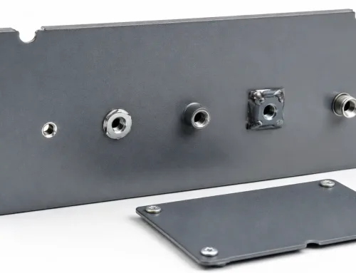
Self-clinching PEM inserts (such as PEM nuts and standoffs) are pressed into the sheet from one side, so the fastener itself does not require access from both sides.
However, the mating screw still needs tool access from the top.
If the insert is placed in a location that becomes inaccessible after other components are installed, the advantage is lost.
Rivets and Blind Fasteners
Rivets and blind fasteners can be set from one side only, which eliminates the need for rear access.
They are useful when the back side of the assembly is blocked by a wall, a mounting surface, or another component.
The tradeoff is that riveted joints are generally not removable for service.
The guiding principle is this: choose the fastener to fit the available access, not the other way around.
If you first select a bolt type and then try to find room for the wrench, you are working backward.
Assembly Sequence and Tool Channel Planning
A sheet metal assembly is not a single part — it is a sequence of operations performed in a specific order.
The order in which components are installed determines which tool channels remain open at each step.
Consider a typical electronics enclosure with a base tray, internal mounting brackets, a PCB, and a cover panel.
If the mounting brackets are fastened from inside the tray, the technician must attach all brackets before dropping in the PCB.
Once the PCB is in place, it blocks access to the bracket screws.
If the design assumes all fasteners are accessible at the end of assembly, the sequence breaks down.
The practical approach is to work backward from the final assembly state:
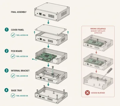
A reverse assembly sequence flowchart illustrating how to verify tool access by working backward from the final assembly state, component by component.
- Start with the last component installed (usually the cover or top panel). Identify its fasteners and confirm tool access exists with everything else already in place.
- Move to the second-to-last component. Confirm its fasteners are accessible with all subsequent components removed but all prior components installed.
- Continue backward through each layer until you reach the first operation.
This reverse-sequence check catches the most common failure mode:
A part that is easy to install individually but impossible to reach after the next component goes in.
In our experience reviewing customer drawings, roughly one in four enclosures has at least one fastener that becomes inaccessible once the assembly sequence is followed.
For multi-level assemblies with stacked internal components, every layer needs its own independent tool path.
A fastener buried under two layers of brackets and wiring is not accessible regardless of how large the opening above it is — the tool cannot navigate the obstacles.
Prototype vs. Production: Different Tools, Different Clearances
The gap between prototype and production tool requirements is a frequent source of surprises.
During the sheet metal prototyping stage, an engineer assembles a few units by hand using manual tools in an open benchtop environment.
The assembly feels straightforward.
Then the design moves to a production line, and the same assembly becomes a recurring problem.
The differences are significant:
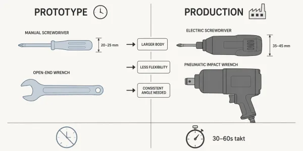
A side-by-side comparison showing the size and capability differences between manual tools used during prototyping and power tools used in production, with key dimensions labeled.
| Factor | Prototype Stage | Production Stage |
|---|---|---|
| Tool type | Manual screwdriver, hand wrench | Electric/pneumatic screwdriver, power wrench |
| Tool size | Smaller, more maneuverable | Larger body, less flexibility |
| Assembly speed target | No time pressure | Takt time of 30–60 seconds per station |
| Technician skill | Engineer who knows the design | Operator following a work instruction |
| Access angle flexibility | Can tilt, rotate, work around obstacles | Needs consistent, repeatable approach angle |
An electric screwdriver used on a production line is typically 35–45 mm in diameter, compared to 20–25 mm for a manual driver.
A power wrench needs both space for its larger socket and clearance for its body.
If the design was validated only with hand tools, these production tools may not fit.
The solution is to include tool access in the mass-production readiness review from the start, even if the first units are assembled by hand.
It is always easier to use a smaller tool in a large space than to fit a larger tool into a space designed for a smaller one.
If production tooling is not yet finalized during the design phase, use conservative clearance estimates — err on the side of more space, not less.
Design Checklist: Tool Access Review Before Drawing Release
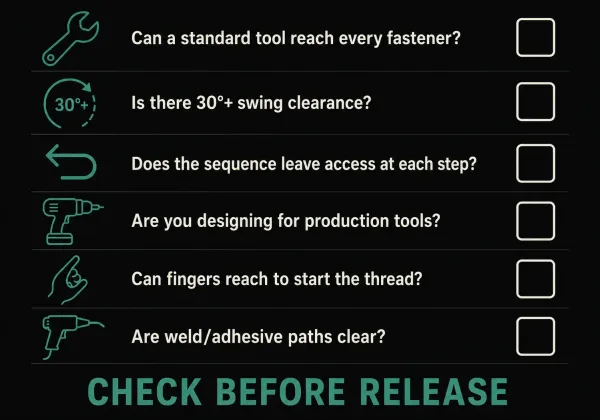
A six-point design checklist for reviewing tool access in sheet metal assemblies before releasing drawings for fabrication.
Before releasing a sheet metal drawing for fabrication, walk through each fastener and assembly operation with these questions:
- Can a standard tool reach every fastener? Place a simplified tool model in your CAD assembly and check for collisions with surrounding geometry.
- Is there enough swing clearance for wrenches? If a spanner cannot rotate at least 30° per stroke, consider switching to a socket head cap screw with vertical hex key access.
- Does the assembly sequence leave every fastener accessible at its installation step? Trace the sequence backward from the final state to confirm.
- Are you designing for production tools, not just hand tools? If the assembly will run on a production line, verify clearance with the actual power tool dimensions.
- Can a worker’s fingers reach the fastener location to start the thread? Deep recesses where fingers cannot align the bolt are a common source of dropped fasteners and cross-threading.
- Are weld or adhesive application paths clear of obstructions? If the assembly includes welding or adhesive bonding, confirm that the gun or applicator nozzle can follow a consistent path.
This checklist does not replace a full design review, but it catches the majority of tool access issues before they reach the shop floor.
FAQs
If you are designing a sheet metal assembly and want a manufacturing review of your tool access and fastener placement, upload your drawing to our team at SR-MFG.
*We will flag access issues before they become production problems.