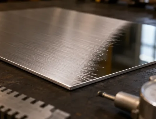
When a Surface Requirement Goes Wrong
A contract manufacturer receives a drawing for a stainless steel enclosure. The title block says “surface requirement per company standard.” The RFQ goes out. The supplier quotes based on their default finish — a standard mill surface with light deburring. Parts arrive. The buyer rejects them: the visible panel face has faint laser cutting lines and the powder coat has minor orange peel. The supplier pushes back: the drawing never specified cosmetic grade, never called out a post-coating roughness limit, and never defined which surfaces were visible in the end product.
This kind of dispute is common, and it almost always traces back to the same root cause: the drawing treated “surface requirement” as a single line item when it is actually a multi-dimensional specification. Understanding what surface requirement covers — and how to write it clearly — prevents this cycle of assumptions, rework, and cost overruns.
What “Surface Requirement” Actually Covers
Surface requirement on an engineering drawing is not a synonym for surface roughness. It is the complete set of expectations for how a part’s surfaces should look, feel, and perform.
In sheet metal fabrication, a surface requirement typically spans three distinct dimensions: roughness, surface treatment, and cosmetic grade. Each dimension answers a different question, and omitting any one of them leaves room for misinterpretation.
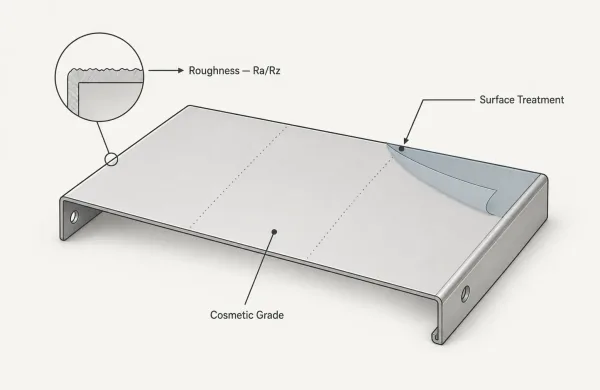
This diagram visualizes the three key dimensions of a surface requirement on a sheet metal part — roughness of the base material, applied surface treatment coating, and cosmetic zone grading of different face areas.
Roughness — the Ra, Rz, and Rq Parameters
Roughness describes the fine-scale texture of a surface — the peaks and valleys left by the manufacturing process.
The most common parameter is Ra (Roughness Average), which measures the arithmetic mean of absolute deviations from the mean line over a defined evaluation length. It is the default callout on most engineering drawings because it is stable, easy to measure, and widely understood across supply chains.
Rz (average maximum height) captures the peak-to-valley extremes over sampling lengths. It is more sensitive to isolated defects — deep scratches, torn material, or tool gouges — that Ra might average away.
For sheet metal parts with sealing surfaces or sliding interfaces, specifying Rz in addition to Ra gives a fuller picture of surface behavior.
Rq (root mean square roughness) weights larger deviations more heavily than Ra because the values are squared before averaging. It appears less often on sheet metal drawings but is useful when a surface must control peak heights for coating adhesion or fluid sealing.
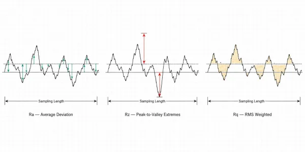
This diagram compares how the three roughness parameters Ra, Rz, and Rq measure different aspects of the same surface profile, showing averaged deviation, peak-to-valley extremes, and root-mean-square weighting respectively.
The key point: roughness is a measurable, quantifiable dimension. It answers the question “how smooth is this surface?”
Surface Treatment — Coating, Plating, and Conversion Layers
Surface treatment refers to the coating or chemical conversion applied to the base metal.
In sheet metal fabrication, common treatments include powder coating, anodizing (for aluminum), electroplating, zinc plating, and passivation (for stainless steel). Each treatment adds a layer — or removes material — and changes the final surface state.
A surface treatment specification should identify the process type, the coating thickness range, and the applicable standard.
For example, a complete powder coating callout would state: “powder coat per ASTM D3359, 60–80 µm thickness.”
“Powder coat black” is not — it leaves thickness, adhesion criteria, and color matching undefined.
Surface treatment answers the question “what is on top of the base metal?”
Cosmetic Grade — Visible Surfaces vs. Non-Visible Zones
Cosmetic grade defines the visual appearance standard for different areas of a part.
Most sheet metal assemblies have a mix of surfaces: some are visible to the end user (front panels, exterior faces), and some are hidden inside an enclosure or against a wall. Treating every surface to the same cosmetic standard is expensive and usually unnecessary.
A practical approach is to divide the part into zones — for example:
- Zone A: visible exterior, no scratches, uniform color
- Zone B: visible but less critical, minor marks acceptable
- Zone C: non-visible, functional surfaces only
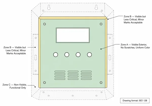
This illustration maps cosmetic zone grading onto a real sheet metal panel, showing how Zone A (visible exterior), Zone B (less critical visible areas), and Zone C (non-visible functional surfaces) are spatially distributed across the part.
This zoning approach lets the manufacturer allocate finishing effort where it actually matters.
Cosmetic grade answers the question “how good does this surface need to look?”
Roughness Parameters That Matter in Sheet Metal
Not every roughness parameter is equally relevant to sheet metal fabrication.
The two surface finish parameters that matter most — and that appear most often on sheet metal drawings — are Ra and Rz.
Ra — the Default, and When It’s Enough
Ra works well for general-purpose surfaces:
- Structural brackets
- Internal mounting faces
- Non-cosmetic panels
A typical sheet metal part made from cold-rolled steel (CRS) with laser cutting and bending will have an Ra in the range of 1.6–6.3 µm on cut edges, depending on laser power, feed rate, and material thickness.
The flat surfaces between cuts will retain the original mill finish of the sheet stock, which is typically Ra 0.8–3.2 µm for standard cold-rolled sheet.
If the part will receive a powder coat or paint finish, the pre-treatment Ra often matters less than the post-coating appearance.
In many cases, specifying Ra on a sheet metal drawing is only necessary for surfaces that interface with gaskets, seals, or mating parts — not for every face.
Rz — When Peaks and Valleys Matter More Than Averages
Rz becomes important on sheet metal surfaces where isolated peaks or valleys cause functional problems.
A common example is a sealing surface on an enclosure: a single deep scratch or laser dross particle might not shift the Ra value significantly, but it could compromise a gasket seal. Rz catches these extremes.
On laser-cut edges, Rz is often more informative than Ra because the cut edge surface has periodic features — striations, dross attachment points — that Ra averages out.
If edge quality is critical, for example, on parts that mate with rubber gaskets or slide into tight channels, specifying a maximum Rz value alongside Ra gives the manufacturer a clearer target.
Surface Treatment vs. Surface Roughness — Two Different Specs
One of the most persistent sources of confusion on engineering drawings is the conflation of surface treatment and surface roughness.
They are not the same thing, and they should not be specified as if they are.
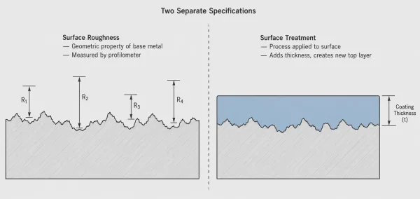
This cross-section comparison shows surface roughness as an inherent geometric property of bare metal (left) versus surface treatment as an applied coating layer that adds thickness (right), emphasizing they are two separate specifications.
Surface roughness is a geometric property of the base material surface. It is measured with a profilometer or optical instrument, and it describes the texture of the metal itself. Roughness exists before any coating is applied.
Surface treatment is a process applied to the surface — powder coating, anodizing, plating, passivation, or chemical conversion. It adds a layer (or modifies the existing surface) and creates a new top surface with its own texture characteristics.
The problem arises when a drawing calls out “surface finish 1.6 µm” without specifying whether that Ra value applies to the bare metal before coating or to the final surface after coating.
Powder coating, for example, typically produces a final surface Ra of 1.6–6.3 µm depending on the powder type and application method.
If the drawing intends a 1.6 µm Ra on the coated surface, the manufacturer needs to select the powder and process accordingly.
If the 1.6 µm applies to the base metal before coating, the manufacturer must achieve that with pre-treatment grinding or polishing — a different operation with different cost implications.
A clear surface requirement separates these two dimensions explicitly: roughness on the base metal as one callout, and surface treatment as a separate specification with its own thickness, adhesion, and appearance criteria.
How Sheet Metal Processes Affect Surface State
Sheet metal fabrication involves a sequence of cutting, forming, and joining operations. Each step leaves its own signature on the part’s surfaces.
Understanding these process signatures helps designers write surface requirements that are achievable without unnecessary cost.
Laser Cutting Edges — HAZ, Dross, and Edge Roughness
Laser cutting produces edges with a characteristic striation pattern — fine parallel lines running along the cut direction.
The roughness of these edges depends on:
- Laser type (fiber vs. CO₂)
- Cutting speed
- Gas pressure
- Material thickness
For mild steel up to 6 mm thick, a fiber laser typically produces cut edges in the Ra 3.2–6.3 µm range.
Two additional surface issues can appear on laser-cut edges:
- Heat-affected zone (HAZ) — a narrow band where the laser’s heat altered the metal’s microstructure
- Dross — resolidified molten metal that adheres to the bottom edge of the cut
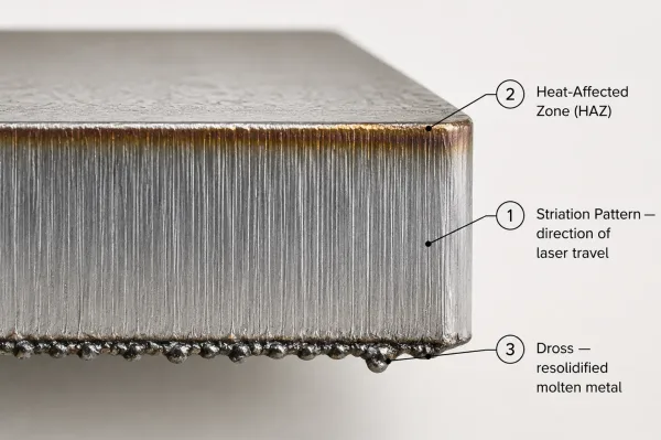
This magnified cross-section of a laser-cut edge highlights three characteristic surface features — striation lines, the heat-affected zone near the cut surface, and dross buildup on the bottom edge.
Dross is usually removed through laser-cut edge deburring, but if the drawing specifies a tight edge roughness without acknowledging that dross removal is a separate operation, the manufacturer may not quote it.
Bending — Outer Surface Stretching and Tool Marks
When sheet metal is bent on a press brake, the outer surface of the bend stretches.
On materials with visible grain direction, this stretching can produce a slight change in surface appearance at the bend line — especially on polished or mirror-finished surfaces. The bend die and punch also leave subtle contact marks on the part surface near the bend.
For most industrial sheet metal parts, these bend-related surface changes are cosmetic and acceptable.
For high-visibility consumer products or medical device housings, the designer may need to specify that bend areas must be free of visible tool marks — which increases manufacturing cost because it requires protective film, polished tooling, or post-bend finishing.
Welding — Heat-Affected Zones and Discoloration
Welding introduces localized heat that discolors the surrounding base metal.
On stainless steel, this discoloration is particularly visible — the heat-affected zone turns blue, gold, or gray depending on the peak temperature and atmospheric exposure.
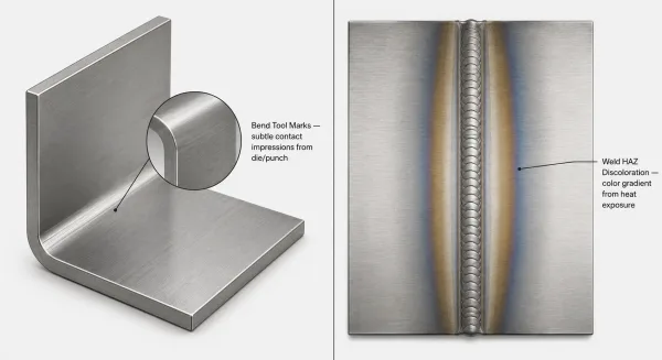
This side-by-side illustration compares two common surface quality issues in sheet metal fabrication: faint press brake tool marks left on bend surfaces (left) and heat-induced color gradient discoloration around welded joints on stainless steel (right).
Standard post-weld cleaning — through pickling, stainless steel passivation, or mechanical grinding — removes this discoloration, but it adds cost and lead time.
If the drawing specifies a cosmetic surface requirement on welded assemblies without addressing weld discoloration, the manufacturer must decide independently whether to clean welds or leave them as-welded.
Specifying the expected post-weld surface state — for example, “weld areas to be ground flush and passivated” — eliminates this ambiguity.
Writing a Clear Surface Requirement Callout
A surface requirement callout on a sheet metal drawing needs three pieces of information: which surface, what specification, and what state.
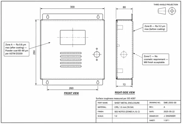
This example engineering drawing demonstrates how to correctly annotate surface requirements on a sheet metal enclosure, with separate callouts specifying roughness values, coating specifications, and cosmetic zone assignments for each surface.
What to Specify: Which Surface, Which Parameter, Which State
Which surface. Identify the specific face or zone that the requirement applies to. Use reference letters, leader lines, or zone maps.
Avoid blanket callouts that apply a single requirement to every surface of the part — this over-specifies non-critical surfaces and drives up cost.
What parameter. State the roughness parameter (Ra, Rz, or both), the value, and the unit.
If the part requires a surface treatment, specify the process type, thickness range, and applicable standard as a separate callout.
What state. Clarify whether the roughness measurement applies to the bare metal (before coating) or the final surface (after coating).
For parts with cosmetic requirements, define in the sheet metal inspection plan whether acceptance is based on visual inspection under specified lighting or instrumental measurement with a profilometer.
Common Mistakes That Cause RFQ Delays
- Blanket Ra on all surfaces. Specifying Ra 1.6 µm on every face of a sheet metal enclosure forces the manufacturer to quote grinding or polishing on surfaces that never see the light of day. Zone your requirements.
- Roughness without surface treatment context. Calling out Ra 0.8 µm on a part that will receive 80 µm of powder coating is contradictory — the coating will change the surface texture. Specify which stage the measurement applies to.
- “Surface finish per spec” with no spec attached. If the company standard is not included in the sheet metal RFQ drawing package, the manufacturer has nothing to work with. Always attach or reference the specific standard document.
- No distinction between cosmetic and functional surfaces. Treating a hidden mounting bracket with the same cosmetic standard as a front panel wastes finishing budget. Use zone grading.
When Tighter Surface Requirements Drive Up Cost
Surface requirements affect manufacturing cost in three ways: processing, inspection, and yield loss.
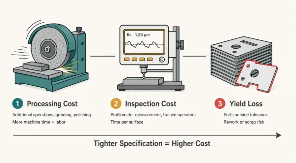
This infographic breaks down how tighter surface requirements increase manufacturing cost through three channels — additional processing operations, more inspection effort, and higher yield loss from out-of-tolerance parts.
Processing Cost
Achieving a finer roughness value usually requires additional operations — more passes with a finer tool, grinding, polishing, or a different cutting process entirely.
A standard laser-cut edge at Ra 6.3 µm costs the base cutting time. Bringing that same edge to Ra 1.6 µm might require secondary grinding, which adds machine time, labor, and tooling cost.
Inspection Cost
If a drawing specifies a roughness value, the manufacturer must verify it.
Surface roughness measurement requires a profilometer or optical roughness gauge, trained operators, and time. Specifying roughness on every surface of a multi-face part multiplies this inspection burden.
Yield Loss
Tighter specifications increase the probability that parts fall outside tolerance.
A part that barely misses an Ra 0.8 µm callout may need rework or scrapping — costs that ultimately flow back into the piece price.
The practical guideline: specify roughness where function demands it (sealing surfaces, sliding interfaces, bearing fits) and leave non-critical surfaces at the process default. This approach controls cost without sacrificing performance.