
Your project manager asks when the IP-rated enclosure prototypes will arrive. The fabricator quotes cutting and bending days. Neither number answers the question.
Design lead time for an IP-rated enclosure is not a machining estimate. It is the combined duration of design freeze, sealing and interface work, sheet metal fabrication, assembly, and whatever ingress checks you need before the sample is actually useful. Teams that treat it as “shop time” under-plan the schedule. Teams that freeze the right items before the RFQ usually recover more calendar days than any rush premium buys.
This guide breaks that timeline into parts you can manage, shows how the target IP level changes the work, and ends with a short set of planning rules for prototype development.
What “Design Lead Time” Actually Covers
For prototype development, “design lead time” should be read as end-to-end elapsed time from a released requirement to a sample you can evaluate. That span usually has four buckets.
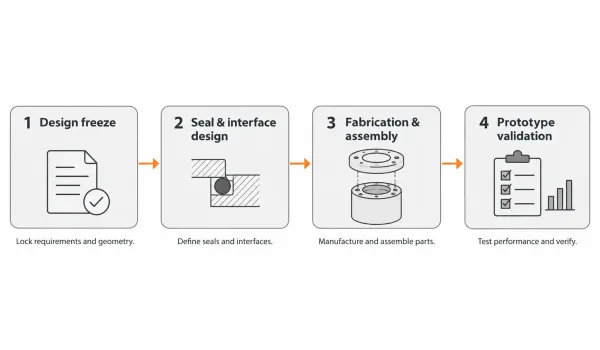
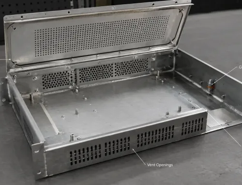
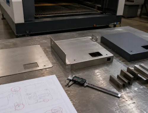
Lead time as four buckets: design freeze, seal and interface design, fabrication and assembly, and prototype validation.
| Bucket | What happens | Typical drivers of duration |
|---|---|---|
| Design freeze | Geometry, interfaces, IP target, seal concept | Requirement clarity, review loops |
| Feature and seal design | Gasket grooves, flange faces, fastener plan, cable entries | IP level, drawing maturity |
| Fabrication and assembly | Laser cut, bend, weld or fasten, finish, fit seals | Part complexity, finish, supplier load |
| Prototype validation | Fit check, leak or spray test, rework if needed | How close the sample is to production intent |
These buckets overlap in a healthy program, but they do not cancel each other. A two-day bend cycle still sits behind an unfinished seal layout. If IP requirements appear only at the end of detailed design, the schedule absorbs a second design pass, not just a thicker gasket.
Design freeze here means more than “CAD looks complete.” It means the sealing strategy, major cutouts, connector list, and acceptance approach are agreed well enough that a supplier can quote and build without reopening the concept.
How the Target IP Level Changes the Work—and the Timeline
IP (Ingress Protection) ratings use two digits: the first describes protection against solid particles, the second against water. The difference that matters for schedule is not the label—it is the design obligation that comes with it.
A modest commercial rating for indoor use may only require a continuous gasket path, controlled flange flatness, and sensible fastener spacing. An outdoor rating such as IP65 (dust-tight and protected against water jets) typically demands tighter control of seal compression, cable-entry hardware that matches the rating, and fewer “we’ll seal it at assembly” improvisations. Higher immersion-oriented targets add still more attention to joint design, process-hole closure, and test method.
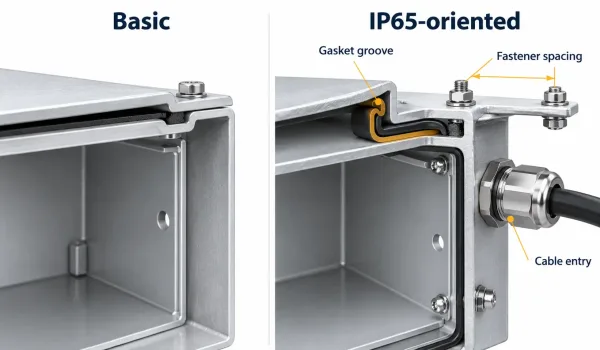
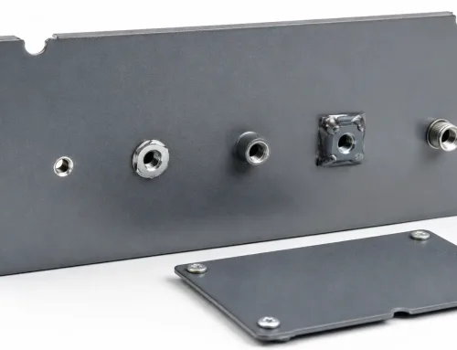
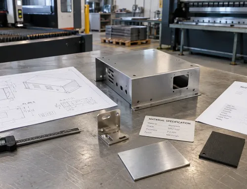
Basic commercial sealing versus IP65-oriented design: controlled groove, fastener spacing, and rated cable entry.
What that does to lead time:
- More design hours before release. Seals, grooves, and interfaces need deliberate geometry, not post-process sealant.
- Fewer acceptable shortcuts. Process holes, unmasked threads, and decorative vents become schedule risks if they are not designed as sealed features.
- More validation thought. Even a simple spray check needs a defined pass/fail idea; otherwise the sample “looks fine” and teaches little.
A useful planning rule: each step up in sealing intent tends to add design and review time first, fabrication time second. The metal itself may barely change. The drawings and the acceptance conversation change a lot.
Prototype Paths Under IP Constraints: What Each One Can Prove
Not every fast prototype can answer an IP question. Choose the path by the decision you need to make, not by the shortest shop clock.
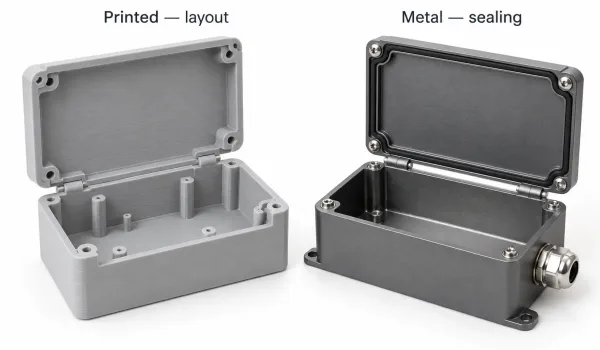
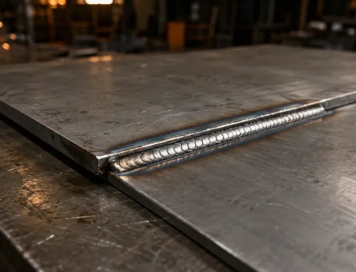
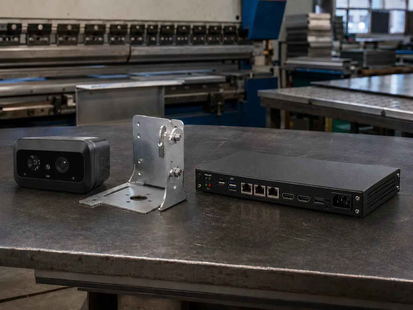
Printed prototype for layout checks versus production-intent sheet metal prototype for seal validation.
| Path | Time scale (planning order) | What it can prove | What it usually cannot prove |
|---|---|---|---|
| Additive / 3D-printed enclosure | Hours to a few days | Fit, cable routing, basic layout | Reliable seal compression, production tolerances, true IP behavior of sheet metal |
| Modified off-the-shelf box | Same day to a few days | Connector placement, early demos | Custom flange sealing, brand-form sheet metal performance |
| Sheet metal prototype with production-intent seals | Typically several business days to about two weeks, depending on finish and assembly | Seal interface behavior, fastener strategy, finish and assembly reality | Full certified IP claim without defined test |
For early layout checks, printing or modifying a stock box is often enough. The moment the decision is “will this gasketed sheet metal joint hold up under the specified IP condition,” the sample should look much like the intended production part: real plate thickness, real bends, real fastener pattern, and a seal that can be installed the way it will be in production.
That distinction matters. A painted 3D print can appear watertight on a bench and still mislead the team on flange flatness, groove fill, or connector sealing. Prototype “IP readiness” is about fidelity of the critical interfaces, not about the part merely existing.
Sheet Metal Features That Quietly Extend the Schedule
From a manufacturing review standpoint, IP-rated enclosures rarely stall because the laser is slow. They stall because drawing features leave room for interpretation.
The features below show up again and again in RFQs that need extra clarification:
- Seal grooves and flange faces. Groove width and depth must match the seal; mating faces need a flatness story. Vague callouts force questions or, worse, parts that leak and need rework.
- Cable entries, connectors, and vents. Every penetration is a sealing decision. Unspecified glands, membrane vents, or connector series push the project into sourcing and interface redesign after quote.
- Fastener spacing and assembly sequence. Uneven spacing or unreachable screws create seal compression problems that appear only at assembly.
- Process holes and threads. Weld access, lifting holes, and tapped holes must be planned as sealed or sealed-off features. “We’ll plug it later” is a schedule and reliability risk.
- Material thickness and finish build. Thicker plate, weld distortion control, and coating thickness all interact with flange geometry and seal compression.
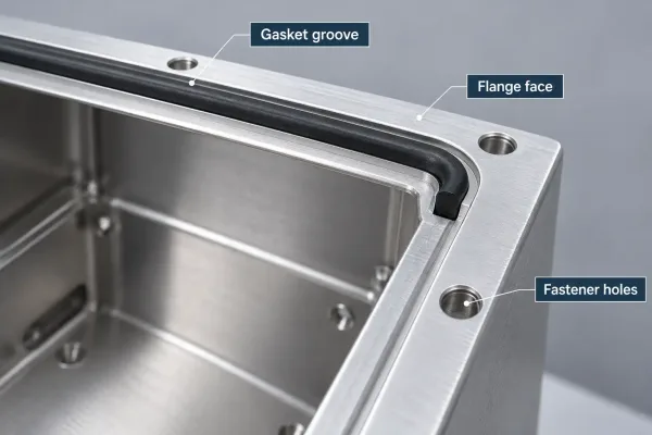
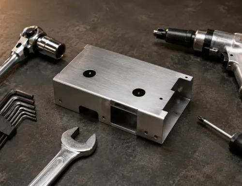
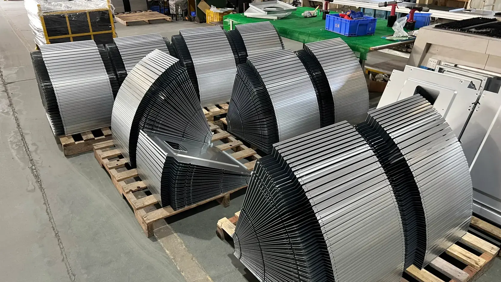
Critical schedule features: gasket groove geometry, flange face, and fastener pattern on sheet metal.
When these items are defined, suppliers can plan the route sheet, tooling (if any), and inspection checks immediately. When they are open, the project spends days in clarification instead of production.
What to Lock Before RFQ to Compress Clarification Cycles
Most delays that look like “supplier lead time” start as incomplete release data. Before you request quotes for an IP-rated prototype, the following should be explicit in the drawing package or RFQ notes:
- Target IP rating and how you will judge it (visual spray check, witness test, or third-party report later).
- Seal approach (gasket type or family, groove or surface seal, serviceable or bonded).
- Material, thickness, and finish—including whether finish applies to sealing surfaces.
- Interface list—connectors, glands, buttons, vents, hinges, and mounting.
- Critical dimensions and seal-related tolerances called out where they matter, not left to general notes alone.
- Prototype quantity and build intent (fit mock-up, functional sample, or near-production pilot).
You do not need a perfect production drawing to start. You need a release package that removes guesswork on sealing and interfaces. That single step is usually the cheapest way to shorten design lead time.
Building a Realistic Prototype Timeline
A workable prototype schedule for an IP-rated sheet metal enclosure often looks like this in planning terms—not as a promise, but as a sequence:
- Requirement and IP target freeze — agree rating, environment, and acceptance approach.
- Layout and seal concept — define flange strategy, penetrations, and assembly method.
- Drawing and RFQ release — include the lock items above.
- DFM feedback and minor design adjustment — one focused loop, not an open-ended redesign.
- Fabrication, finish, and seal installation — the shop’s core build window.
- Prototype check — fit, fastener compression, and a defined ingress check if required.
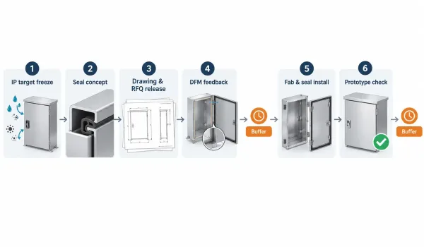
Planning sequence: freeze IP target, define seal concept, release RFQ, DFM loop, build, then prototype check.
Buffer belongs after step 4 and after step 6, not only at the end of the project. If the sample’s job is to validate sealing, plan at least one controlled rework window; IP prototypes teach through first-pass failures more often than teams admit.
Planning rules for the next build
- Freeze the sealing strategy before you ask for a date.
- Match prototype fidelity to the decision: layout can be low-fidelity; sealing should be production-intent.
- Treat every penetration as a designed interface.
- Put acceptance language in the RFQ, even if the formal test comes later.
- Ask the supplier which features they will interpret if the drawing stays silent—then remove those interpretations from the drawing.
If you are preparing an RFQ for IP-rated sheet metal enclosures, a short DFM review of seal interfaces and callouts before release will usually remove more calendar days than any rush fee.
FAQs