
A rivet nut can look fully installed and still fail the joint. The flange sits flat, nothing appears tilted, and the screw starts by hand — yet the installed height is outside the range the assembly needs, and the connection will loosen, strip, or interfere later. Installation height is not a visual courtesy check. It is a measured control dimension that tells you whether the fastener set correctly, whether the grip matches the panel stack, and whether the mating part will sit where the drawing intends.
This guide explains what installation height actually measures, how to inspect it on sheet metal assemblies, and how to turn height readings into acceptance decisions instead of arguments.
Why “it looks installed” fails as an inspection
Most rivet nut disputes start the same way. The fabricator says the parts look fine. The buyer says the covers will not seat or the screws bottom out. Both are describing the same installation — and both can be right about what they see.
Visual checks catch gross failures: a cocked head, a cracked panel, a thread that will not accept the screw. They do not catch a body that collapsed 0.4 mm short, a head that stands proud because the panel was thicker than the grip range, or a batch that drifted because tool pressure changed mid-shift.
Those smaller deviations rarely announce themselves at the workstation. They show up at assembly, in the field, or as a quality escape. That is why installation height needs the same discipline as any other controlled dimension on a formed sheet metal part.
What installation height actually measures
Rivet nut catalogs list several height-related dimensions. They are not interchangeable. Confusing them is the most common source of “the drawing says one thing and the part measures another” arguments.
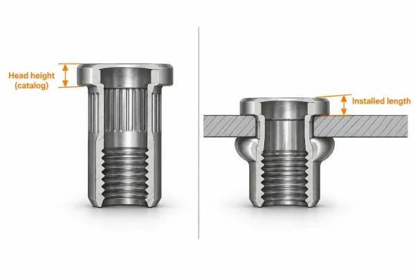
Side-by-side cutaway labels show catalog head height before installation versus installed length after setting.
Head height versus installed length
Head height (or flange thickness) is a pre-install dimension of the fastener itself — how thick the seating head is before anything is set. It is useful for clearance above the panel, but it does not describe the finished joint.
Installed length is the post-install dimension: the height of the fastener assembly after setting, measured from a defined reference face on the panel to a defined face on the rivet nut. This is usually what people mean by installation height in inspection contexts.
A low-profile head can still produce a tall installed length if the body does not collapse fully. A standard head can sit lower than expected if the panel is soft and the head embeds. Read the catalog dimensions as inputs. Inspect the installed result.
Where the measurement sits in the joint stack
Think of the fastened joint as a stack:
- Mating component thickness
- Any gap or standoff intended by design
- Rivet nut projection above the panel (installed height / head area)
- Panel thickness at the hole
- Collapsed body / under-head grip on the blind side
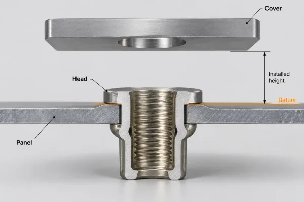
Cross-section of a rivet nut joint marks the seating-face datum and installed height above the panel.
Installation height inspection focuses on (3), with (4) as the datum. If the design assumes a flush cover, a spacer, or a specific thread engagement depth, the installed height has a functional job — not just an aesthetic one.
How height deviation affects the joint
Height is a proxy for set quality. When it drifts, one of three things is usually wrong: the collapse, the grip, or the seating.
- Too tall (under-set): The body did not form a full closing head. Clamp load is low. The rivet nut may spin under torque, loosen under vibration, or pull out at a fraction of catalog values.
- Too short (over-set or embedment): Excessive force crushed the body, pulled the head into a soft panel, or the wrong grip range was used for a thin stack. Threads may be distorted even if the screw still starts.
- Uneven across a batch: Tool pressure, mandrel wear, hole diameter, or panel thickness is drifting. Individual parts may pass a loose visual check while the process is already out of control.
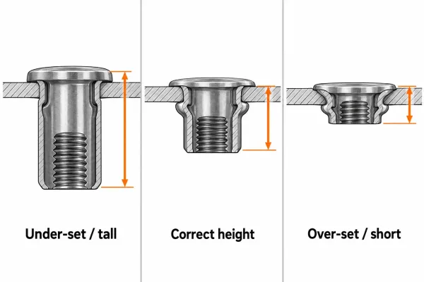
Three cross-sections compare under-set, correct, and over-set rivet nut heights with short labels.
Assembly fit suffers first. A cover that relies on a precise stack will rock or gap. A screw sized for a specific engagement may bottom out or fail to reach full threads. Height is rarely the only problem — it is often the earliest readable symptom.
How to measure installation height correctly
You do not need a laboratory. You need a defined method and a habit of using it the same way every time.
Tools and resolution
Use a caliper with at least 0.02 mm (0.001″) resolution for routine checks. A height gauge on a surface plate is better for first-article work or when the panel face is not a reliable hand datum. Avoid tape measures, rough scales, or “close enough” comparisons to a sample part without numbers.
Zero and clean the jaws. Confirm the tool is in calibration if the reading will be used for acceptance.
Reference faces and method
Agree two faces before the first part is measured:
- Lower reference: the panel face where the head seats (front face), or a machined/fixture datum if the panel is warped.
- Upper reference: the top of the head/flange, or the top of the body if the design calls out body projection rather than head height.
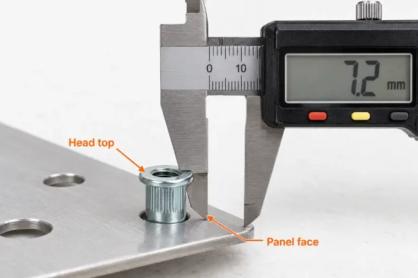
Caliper jaws contact the panel seating face and the top of the rivet nut head to read installed height.
Measure perpendicular to the panel. Do not average in tilt by rocking the caliper. If the head is countersunk or reduced-profile, use the face the drawing specifies — not the highest point you can find.
Record the dimension the drawing names. “Height” without a datum is not a measurement.
When to measure in the process
- First article / setup: every specified height feature, before production release.
- During production: at a defined sample rate (for example first piece per shift, every N parts, or after any tool or material change).
- After material or coating changes: coatings add thickness. If the acceptance range does not include finish, re-baseline the reading.
- At incoming inspection (outsourced inserts or sub-assemblies): treat installed height as a lot characteristic, not a one-off shop note.
How to specify acceptance on drawings
If height matters to fit or function, it belongs on the drawing or in the inspection plan. “Install neatly” is not a specification.
Where the tolerance comes from
Build the range from the stack-up, not from habit:
- Nominal installed height from the fastener + panel combination
- Manufacturing variation of the fastener (head height tolerance, body length)
- Installation process capability (tool stroke/force, operator, hole quality)
- Functional allowance (clearance, flushness, thread engagement)
Start from the fastener manufacturer’s installed-length data when available. Tighten only where the assembly function requires it. A tighter height callout than the joint needs is cost without benefit.
Callout examples
Practical callouts state the dimension, the datum, and the limit:
- Installed height from panel face to head top: 2.8 ± 0.3 mm
- Projection above outer surface: max 1.2 mm after finish
- Installed length per catalog, measured from seating face; 100% at FAI, 1 per 50 in production
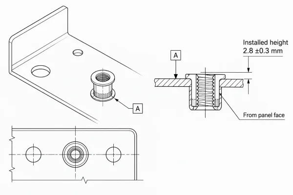
A simple sheet metal drawing callout shows installed height with datum and tolerance.
Include the measurement method if there is room for interpretation (caliper vs height gauge, before or after coating).
Pass / deviation / reject boundaries
| Outcome | Typical meaning | Action |
|---|---|---|
| Within tolerance | Set and grip look correct | Accept |
| Outside tolerance, joint function still met | Process drift or conservative limit | Deviation review; adjust process |
| Outside tolerance, fit or engagement affected | Under-set, over-set, or wrong grip | Reject or rework if allowed; fix cause before more parts |
Do not release a lot solely because “most parts look fine.” Height is a cheap check compared with an assembly line stop.
What out-of-spec heights are telling you
Treat height data as a process signal, not only a pass/fail stamp.
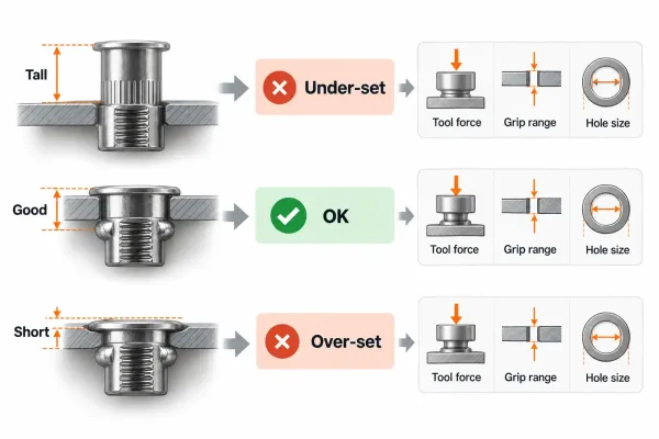
Height reading patterns map to likely causes such as under-set, over-set, and tool drift.
| Reading pattern | Likely cause | What to check first |
|---|---|---|
| Consistently tall | Under-set; insufficient pull; wrong grip for thick panel | Tool force/stroke; grip range vs actual stack (including coating) |
| Consistently short | Over-set; soft panel embedment; too-small grip | Reduce force; verify panel hardness; head style vs panel |
| High scatter in one lot | Hole size variation; mandrel wear; mixed panels | Hole tolerance; tool maintenance; material lot |
| Good height, poor torque-out | Body form or hole fit issue | Body style (smooth vs knurled/hex); hole diameter |
| Height changes after coating | Finish thickness not in the stack | Update nominal and tolerance for finished condition |
Fix the cause at the tool, the hole, or the specification. Sorting parts without a process correction only moves the problem.
FAI versus production: what to check when
First article (FAI): confirm the full definition — installed height on all specified features, head seating, thread go/no-go, anti-rotation (light torque check), and visual condition of the panel. Compare against the drawing callout, not only the sample “golden part.”
Production: keep the checks that catch drift. Height on a sample, thread function on a sample, and a short visual scan are usually enough if FAI was sound. Increase frequency after tool changes, material changes, or any height out-of-tolerance event.
For buyers and design engineers, the practical control is the same: state what will be measured, how often, and what happens on a fail. Ambiguity at RFQ becomes rework at delivery.
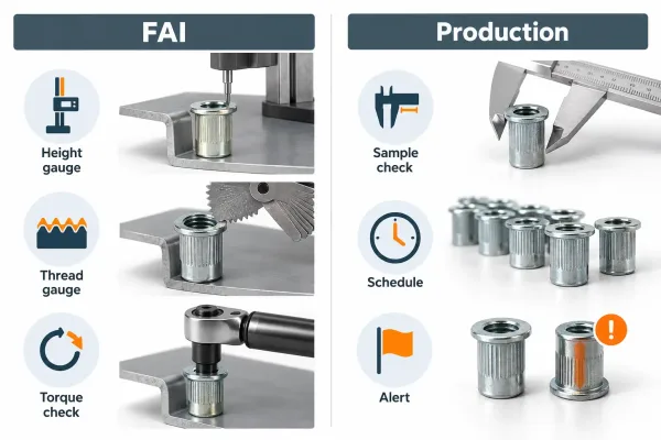
Two-column graphic compares first-article height checks with production sample checks.
Installation height inspection checklist
Use this as a working list at drawing release, RFQ, or incoming inspection.
- Dimension name is defined (installed length / projection / head height) with a datum.
- Nominal and tolerance reflect panel thickness including finish.
- Grip range matches the real stack, not the nominal sheet callout alone.
- Measurement tool and resolution are agreed (caliper or height gauge).
- Reference faces are written down and used the same way every time.
- FAI measures height, seating, thread, and anti-rotation before production.
- Production sample rate and reaction plan are defined.
- Out-of-spec height triggers cause analysis (force, hole, grip, material), not only sorting.
- Supplier catalog installed-length data is on file for the exact part number.
- Any change to coating, panel, or tool re-baselines the height check.
If height is on the drawing, it should be inspectable. If it is not inspectable, it is not yet a requirement.
FAQs
For sheet metal assemblies where fastener installation is part of your print package, a clear height callout and inspection plan at RFQ stage prevents most “installed but wrong” disputes. SR-MFG can review drawings and process assumptions with your team before the first batch.