In the mechanical industry, fillets and chamfers are like a pair of “twins.” At first glance, both are used to treat sharp edges, but in practice, they are completely different. Use the right one, and a part’s service life may double. Use the wrong one, and an entire production batch could end up scrapped.
1. First, Understand the Difference Between a Fillet and a Chamfer
Many people who have worked in the industry for three to five years still may not be able to explain the difference clearly. Let’s start by looking directly at their geometric features.
Illustration of the Differences in Geometric Features
| Comparison | Fillet (R Corner) | Chamfer |
|---|---|---|
| Geometry | Rounded arc transition | Inclined flat surface (45°/30°/60°) |
| Main Function | Distributes stress and prevents fatigue fracture | Facilitates assembly, removes burrs, and guides fluid flow |
| Typical Applications | Crankshaft journals, aerospace blades, mold cavities | Threaded hole openings, pipe fittings, electronic connectors |
| Load Characteristics | Preferred for cyclic loads and impact loads | Preferred for static loads and assembly guidance |
| Machining Difficulty | Higher (requires form tools, ball-end mills, or grinding) | Lower (can be produced by turning, milling, filing, or chamfering machines) |
| Appearance | Smooth, rounded, and comfortable to the touch | Clean, precise, and industrial-looking |
In one sentence: use a fillet when you are worried about fracture, and use a chamfer when you are worried about assembly.
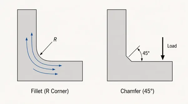
This diagram presents a side-by-side cross-section comparison of a fillet (smooth arc transition) and a chamfer (45-degree angled cut) at a joint corner, with dimension annotations to highlight their geometric differences.
2. Design Selection: These Three Factors Determine Your Choice
If your part is subjected to cyclic loads or impact forces, a fillet is essential. There is really no room for compromise.
On the other hand, if the part only carries static loads or is simply a connecting component, a chamfer is usually enough and can often be handled as a straightforward edge-finishing operation. It saves both cost and machining time.
Do not underestimate this detail. A customer may touch the part once and decide not to place the order.
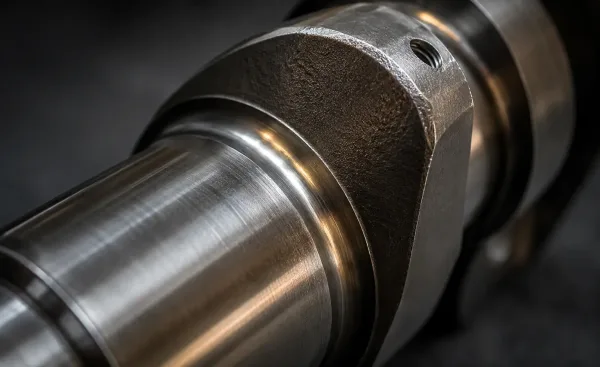
This close-up highlights the smooth fillet radius at the junction between a crankshaft journal and the crank web, demonstrating the type of critical edge treatment used to prevent fatigue fracture under cyclic loading.
3. Machining Processes: Don’t Understand Design Without Understanding Manufacturing
| Process Type | Fillet Machining | Chamfer Machining |
|---|---|---|
| Turning | Form turning tool / circular interpolation (suitable for rotational parts) | Adjust the tool angle to produce the chamfer quickly |
| Milling | Ball-end mill / form milling cutter (suitable for complex surfaces) | End mill / chamfer mill |
| Grinding | Suitable for bearing-race-level precision | Generally not used |
| EDM | Used for high-hardness materials and complex mold fillets | Rarely used |
| Manual Work | Almost impractical | Hand filing by a fitter, suitable for small batches |
| Dedicated Equipment | None | Chamfering machines for automated high-volume production |
A reminder from experienced engineers: when reviewing a part for design for manufacturability, think about whether the workshop actually has the right tool for the job. Don’t draw something that cannot be manufactured.
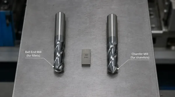
This image compares the two key CNC milling cutters used for edge treatment: the ball-end mill with its rounded tip for machining fillets, and the chamfer mill with its angled tip for cutting chamfers.
4. Avoid These Common Mistakes
Mistake 1: Using a chamfer where a fillet should be used
Result: stress concentration → fatigue cracks → fracture and scrap. An RMB 800,000 lesson came from exactly this kind of mistake.
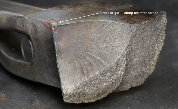
This macro photograph documents a fatigue crack that initiated at a sharp chamfer corner on a steel component, showing classic beach marks and crack propagation patterns — a real-world consequence of using a chamfer where a fillet should have been specified.
Mistake 2: Specifying the fillet radius arbitrarily
Result: if the fillet is too large, it may interfere with mating parts and prevent assembly. If it is too small, it will not distribute enough stress, making the fillet almost pointless.
Mistake 3: Choosing chamfer angles randomly
Use a 60° chamfer at the opening of a threaded hole, and the screw may not even start properly. Standard components have standard angles. Don’t invent your own.
Mistake 4: Focusing only on function and ignoring machining cost
The grinding cost of a precision fillet can be ten times that of a chamfer. Design is the first stage of cost control.
5. Practical Quick Reference: What to Choose in Common Situations
| Application | Recommended Choice | Reason |
|---|---|---|
| Crankshafts, connecting rods, gear roots | Fillet | Cyclic loading and fatigue prevention |
| Threaded hole openings, bolt heads | Chamfer | Assembly guidance and burr removal |
| Mold cavity edges | Fillet | Smoother material flow and better forming quality |
| Pipe fittings, flange end faces | Chamfer | Sealing alignment and weld preparation |
| Consumer electronics housing edges | Large fillet | Better feel and appearance |
| Ends of precision shaft-hole fits | Small fillet or none | Avoids interference during assembly |
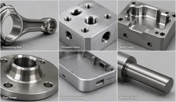
This gallery presents six real-world examples of edge treatment choices — fillets on connecting rods and mold cavities, chamfers on threaded holes and pipe flanges, large fillets on electronics housings, and minimal fillets on precision shafts — matching the quick-reference guide in the article.