Why Most People Get Process Planning Wrong
When engineers and buyers hear “process planning,” they tend to picture a manufacturing team sitting down with a finished drawing and mapping out how to make the part.
The drawing is done. The design is locked. Now the factory figures out the rest.
That picture is not wrong — but it misses the most important part.
Process planning does not begin when a drawing lands on a shop floor desk. It begins the moment a designer chooses a material, specifies a tolerance, or adds a feature that requires a particular manufacturing method.
Every one of those decisions constrains or expands what a manufacturer can do, how much it will cost, and how long it will take.
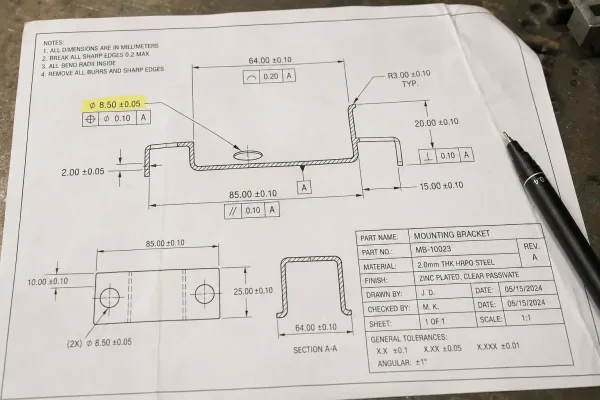
A macro photograph of an engineering drawing detail area, highlighting dimension lines with tolerance values, GD&T symbols, and material callout blocks that directly influence how a manufacturer plans production.
A tight tolerance on a non-critical feature might look harmless on screen, but it can force a shop to change cutting methods, add inspection steps, or reorder an entire production sequence.
The distinction matters because it shifts responsibility.
If process planning is purely the manufacturer’s job, then a buyer’s only role is to send a drawing and wait.
Because process planning is shaped by design decisions, good sheet metal RFQ preparation directly affects how accurately a manufacturer can plan, quote, and deliver.
Understanding process planning is not just useful for manufacturing engineers. It is useful for anyone who specifies, sources, or approves sheet metal parts.
What Process Planning Actually Covers
Process planning is the systematic determination of how a product will be manufactured.
It translates a design — usually expressed as a CAD model or technical drawing — into a defined sequence of manufacturing operations, each with specified equipment, tooling, and quality checkpoints.
The term covers more than just picking a list of machines. A complete process plan addresses several interconnected decisions:
- Manufacturing method selection — choosing which processes (laser cutting, punching, bending, welding, and so on) will produce the part to specification.
- Operation sequencing — determining the order in which those processes are performed, accounting for geometric dependencies and fixture constraints.
- Equipment and tooling — matching each operation to specific machines, dies, punches, and fixtures that can achieve the required accuracy.
- Quality checkpoints — defining where and how dimensional and surface inspections are performed during production.
- Time and cost estimation — calculating cycle times, setup times, and material usage to support quoting and scheduling.
In practice, process planning is the link between a design intent and a physical part.
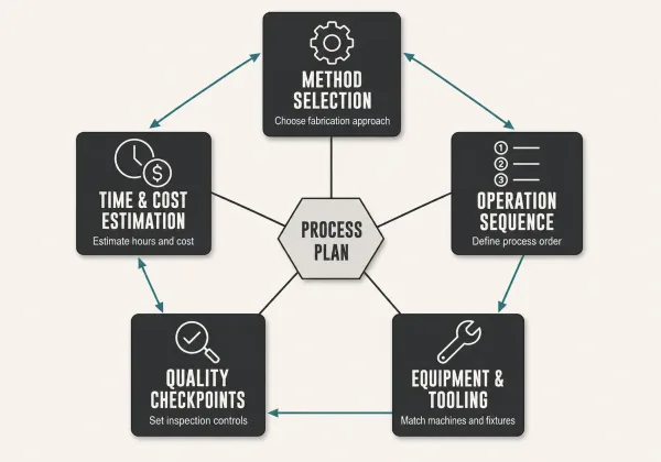
A clean technical diagram illustrating the five core components of process planning, with each component represented as a connected node showing how decisions in one area affect the others.
It answers the question: given this drawing, what is the most efficient and reliable way to make it?
The Core Steps in Process Planning
While the specifics vary by industry and part complexity, most process planning efforts follow a recognizable sequence of steps:
1. Analyze the drawing and specifications.
The planner reviews dimensions, tolerances, material callouts, surface finish requirements, and any special notes (heat treatment, plating, testing).
This step is about understanding what the part demands before deciding how to make it.
2. Select manufacturing processes.
Based on the geometry, material, thickness, and tolerances, the planner chooses which processes are needed.
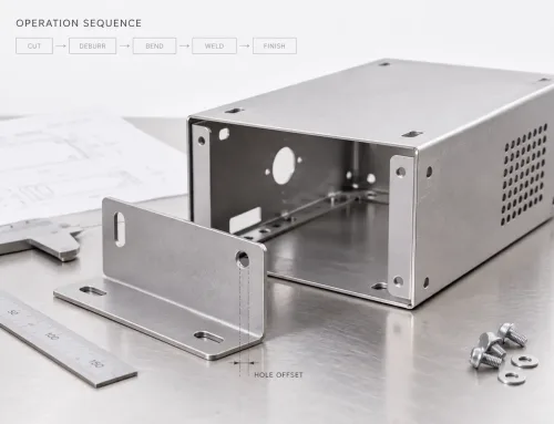
For a sheet metal part, this might mean laser cutting for the flat profile, press brake bending for formed features, and spot welding for assembly.
When tighter tolerances or three-dimensional features cannot be produced efficiently with sheet metal processes alone, manufacturers may use CNC machining services for milled pockets, precision bores, threaded features, or critical datum surfaces.
3. Determine the operation sequence.
The order of operations matters.
Bending before welding, for example, changes how parts are fixtured. Cutting after forming may be necessary when formed features affect the flat pattern.
The planner maps out a sequence that avoids interference and minimizes rehandling.
4. Assign equipment and tooling.
Each operation is matched to a specific machine and tool set.
A press brake needs the right punch and die combination for the material and thickness. A laser cutter needs the correct nozzle and gas settings for the cut quality required.
5. Define inspection points.
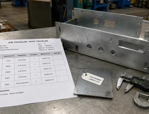
A sheet metal inspection plan assigns critical dimensions, bend angles, hole positions, and surface finish requirements to the appropriate inspection stage — either in-process or final.
6. Estimate time and cost.
The planner calculates setup time, cycle time per part, material consumption, and any secondary operations.
This feeds directly into the quotation and production schedule.
Each step feeds into the next. A decision made at step two (process selection) constrains what is possible at step three (sequencing) and step four (tooling).
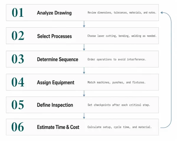
A vertical flowchart showing the six sequential steps of process planning, with each step connected by arrows and brief descriptions of what each step involves.
This interdependency is why process planning requires experience, not just a checklist.
How Process Planning Works in Sheet Metal Fabrication
The general framework above applies to all manufacturing.
In custom sheet metal fabrication, process planning has a distinct character because the operations are highly sequential and geometrically interdependent.
Cutting comes first — but the choice is not obvious.
A flat sheet metal part starts with cutting the blank profile.
Laser cutting, waterjet cutting, and plasma cutting can all do this, but the right choice depends on material type, thickness, edge quality requirements, and production volume.
A 2 mm stainless steel bracket with tight edge tolerances calls for laser cutting. A 25 mm aluminum plate might be better suited to waterjet.
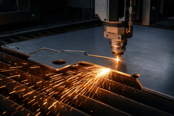
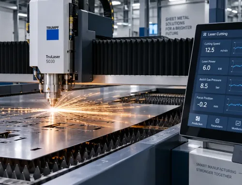
A close-up photograph of a fiber laser cutting head piercing through a stainless steel sheet, producing a bright trail of molten sparks along the cutting path, demonstrating the first step in sheet metal process planning.
The process plan must account for this before anything else.
Bending sequence is the most planning-intensive step.
In sheet metal, bending is where process planning gets complex.
The order in which bends are made affects which flanges are accessible, how the part is fixtured, and whether earlier bends interfere with later ones.
A part with four bends might have dozens of possible sequences, but only a few that are physically feasible without custom tooling.
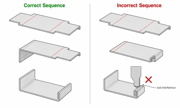
A side-by-side technical diagram comparing two bending sequences for the same sheet metal part — one showing correct order with accessible flanges and one showing incorrect order causing tool interference.
The planner must also select the correct punch and die profile based on material thickness and bend radius requirements — getting this wrong leads to cracking, warping, or dimensional errors.
Secondary operations follow a logical hierarchy.
After cutting and bending, operations like welding, hardware insertion (PEM fasteners, rivets), tapping, and deburring are sequenced based on access and geometry.
Welding, for example, is typically done before surface finishing because heat and spatter can damage coatings.
Hardware insertion requires access to specific surfaces, which may be blocked after bending.
Surface finishing is planned, not assumed.
Powder coating, anodizing, painting, or plating — each has pre-treatment requirements, masking needs, and dimensional implications (coating thickness adds to part dimensions).
The process plan specifies which surfaces are finished, which are masked, and what preparation steps are required.
Inspection is integrated, not appended.
Dimensional checks are scheduled at points where errors can still be corrected:
- after cutting (blank accuracy),
- after bending (bend angle and flange length),
- and after finishing (coating thickness, surface defects).
Final inspection confirms the part meets the drawing before it ships.
This is why two fabrication shops can receive the same drawing and produce the same part with different process plans — and why the quality of that plan affects everything from cost to delivery reliability.
Process Planning vs. Production Planning: What’s the Difference?
The terms are often used interchangeably, but they address different questions.
Process planning answers: How will this part be made?
It defines the manufacturing method, operation sequence, tooling, and quality checkpoints for a specific part or assembly.
Production planning answers: When and how much?
It deals with demand forecasting, capacity allocation, scheduling, inventory management, and delivery timelines.
The two functions are complementary.
A process plan tells you that a part needs laser cutting followed by three bends and powder coating.
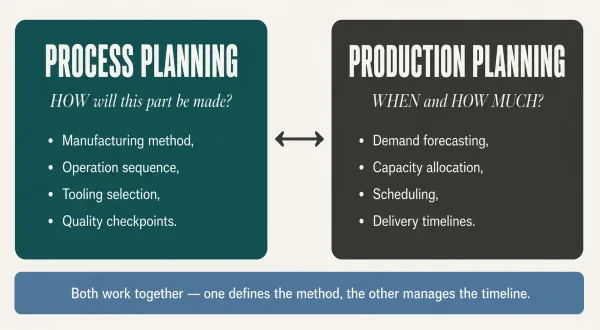
A two-column comparison diagram showing process planning on the left (focused on HOW a part is made) and production planning on the right (focused on WHEN and HOW MUCH), with their respective key outputs listed below each.
A production plan tells you when that part will be cut, bent, coated, and shipped — and whether the shop has capacity to do it by the requested date.
In small fabrication shops, the same person or team may handle both. In larger operations, they are typically separate functions.
For buyers, the practical distinction is this: when you submit an RFQ, you are initiating a process plan (how will this be made?) that feeds into a production plan (when can it be delivered?).
How Process Planning Affects Your Quote and Lead Time
For buyers and engineers, the most relevant aspect of process planning is its direct impact on cost and delivery.
Complexity drives cost.
A part with five bends, two welded assemblies, and a masked powder coat finish requires more process planning effort than a flat laser-cut bracket.
Each additional operation adds setup time, tooling requirements, and inspection points.
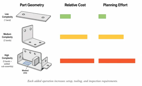
A simple infographic showing three sheet metal parts of increasing complexity alongside their corresponding cost and planning effort levels, demonstrating why complex parts cost more to produce.
When a manufacturer quotes a complex part, the price reflects not just machine time but the planning and coordination required to execute it reliably.
Ambiguity extends lead time.
When a drawing is incomplete — missing material specifications, unclear tolerance zones, or ambiguous surface finish requirements — the manufacturer must either make assumptions (risky) or request clarification (slow).
Both outcomes extend the time between RFQ submission and firm quote delivery.
A well-specified drawing reduces back-and-forth and allows the manufacturer to commit to a process plan faster.
Process planning catches design issues early.
During the planning phase, an experienced engineer reviews the drawing for manufacturability.
They may flag features that are difficult to form, tolerances that are tighter than necessary, or assembly sequences that will cause problems in production.
A sheet metal DFM review, when performed and communicated early, can save both parties time and cost.
A manufacturer that skips this step may quote faster — but the problems surface later, during production, where they are far more expensive to fix.
What Buyers Can Do to Support Better Process Planning
Buyers cannot — and should not — do the manufacturer’s process planning.
But they can provide the inputs that make planning more accurate and more efficient.
Specify materials completely.
“Steel” is not a specification.
“Cold-rolled steel, ASTM A1008, 1.5 mm thick” gives the planner what they need to select the right cutting parameters, bend tooling, and surface treatment.
Call out critical dimensions and tolerances.
Not every dimension on a drawing is equally important.
Identifying which features are critical — and which can default to standard tolerances (ISO 2768, for example) — lets the planner focus inspection and process control where it matters.
State surface finish requirements explicitly.
If a part needs powder coating, specify the color, thickness, and any masking requirements.
If surfaces must be left bare, say so.
Ambiguity here forces assumptions that may not match expectations.
Indicate volume and delivery expectations.
A prototype run of 5 pieces and a production run of 5,000 may require different process plans.
Tooling that is cost-effective at volume may not justify its setup cost for a small batch.
Sharing volume intent at the quoting stage helps the manufacturer plan appropriately.
These are not extra steps — they are the minimum information a manufacturer needs to plan your part’s production path accurately.
The more complete the input, the more reliable the process plan — and the more predictable the cost, quality, and delivery.
FAQs
Process planning is the bridge between a design on screen and a part in hand.
Understanding how it works — and what inputs it needs — helps engineers and buyers make better decisions at every stage, from first sketch to final shipment.
If you have a design you’d like reviewed for manufacturability, submit your drawings to SR-MFG for a process-driven quote.