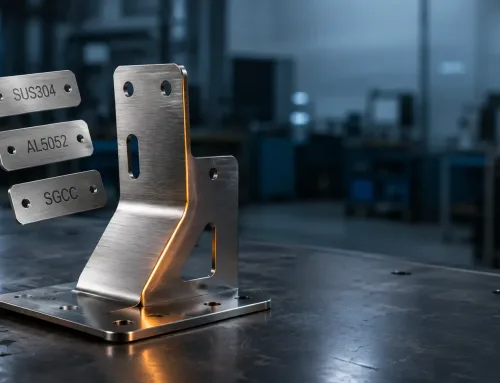
Every sheet of metal you order has a nominal thickness — 1.0 mm, 2.0 mm, 3.0 mm, and so on. But the actual thickness of the sheet you receive will not be exactly that number. It will be slightly above or slightly below, and that allowable deviation is what engineers call thickness tolerance.
Understanding sheet metal thickness in design matters because it affects how parts fit together, how welds hold, and whether your supplier delivers material you can actually use. This guide explains where thickness tolerance comes from, what the common standards say, and how to specify it correctly on your drawings.
Where Does Thickness Tolerance Comes From
Thickness tolerance is not an arbitrary number a mill chooses. It is a direct consequence of how flat-rolled metal is produced.
Rolling Process Variables
During hot or cold rolling, metal passes through a series of rollers that reduce its thickness to the target dimension. Several variables make it physically impossible to hold exact thickness across every point of every coil:
- Roll gap precision — the spacing between rollers fluctuates slightly due to thermal expansion and mechanical wear.
- Incoming slab variation — the starting thickness of the cast slab or hot band is never perfectly uniform.
- Material springback — after passing through the rollers, the metal elasticallies recovers a small amount, and this recovery varies across the width and length of the sheet.
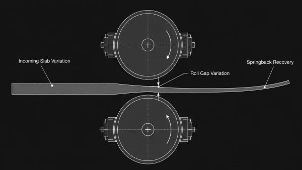
Three inherent variables in the rolling process — roll gap, incoming slab variation, and springback — make exact thickness control physically impossible.
These variables are inherent to the rolling process. A tighter tolerance is achievable, but it requires more passes, slower line speeds, and more frequent gauge checks — all of which increase cost.
Why Thicker Material Has Wider Tolerance
As sheet metal thickness increases, the absolute tolerance band also increases. A 0.5 mm sheet might carry a tolerance of ±0.03 mm, while a 6.0 mm plate might carry ±0.20 mm or more.
This is because the rolling force required to deform thicker stock is greater, and small variations in force produce larger absolute deviations. The ratio of tolerance to nominal thickness actually stays relatively constant, but the absolute number grows.
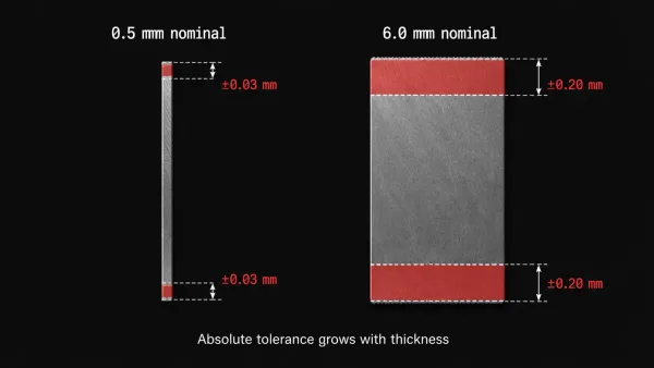
As nominal thickness increases, the absolute tolerance band widens — a 0.5 mm sheet may hold ±0.03 mm while a 6.0 mm plate may allow ±0.20 mm.
Common Standards for Thickness Tolerance
When you specify a material grade and thickness on a drawing, the applicable tolerance depends on which standard governs that material. Different standards organizations publish their own tolerance tables, and the values are not always identical.
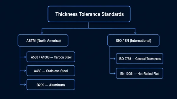
Key thickness tolerance standards are organized by region and material type — ASTM standards dominate North American practice while ISO and EN standards are used internationally.
ASTM Standards for Steel Sheet and Plate
In North America, the most widely referenced standards are:
- ASTM A568 / A1008 — covers hot-rolled and cold-rolled carbon steel sheet. Tolerance values depend on thickness range, width, and whether the sheet is cut-edge or mill-edge.
- ASTM A480 — covers stainless steel sheet, strip, and plate. Tolerances are specified separately for hot-rolled and cold-rolled products.
Typical thickness tolerances under ASTM A480 for cold-rolled stainless sheet (width < 1250 mm) range from ±0.01 mm for material under 0.20 mm thick to ±0.07 mm for material 2.50–3.00 mm thick.
ISO and EN Standards for General Tolerances
- ISO 2768-1 — defines general tolerances for linear and angular dimensions, including thickness, when no specific tolerance is given on the drawing. It defines four tolerance classes: f (fine), m (medium), c (coarse), and v (very coarse).
- EN 10051 — specifies thickness tolerances for hot-rolled uncoated flat steel products.
ISO 2768 is frequently used as a default on engineering drawings. When you see a title block referencing “ISO 2768-m,” the thickness tolerance for dimensions up to 30 mm is typically ±0.2 mm under the medium class.
How to Read a Tolerance Table in a Material Spec
Tolerance tables in material standards are organized by thickness range and, often, by sheet width. Wider sheets typically have slightly wider tolerances because the rolling process has less control over edge-to-edge gauge variation.
When looking up a value, find the row that matches your nominal thickness and the column that matches your sheet width — the intersection gives you the applicable ± tolerance.
Thickness Tolerance by Material
Different metals behave differently during rolling, so their thickness tolerances vary. The tables below summarize typical ranges for common sheet metal materials.
Carbon Steel
Cold-rolled carbon steel sheet (ASTM A1008) typically carries tighter tolerances than hot-rolled (ASTM A1011) because the cold rolling process allows finer gauge control.
For a 1.0 mm cold-rolled sheet under 1000 mm wide, the typical tolerance is ±0.05 mm. The same nominal thickness in hot-rolled form might be ±0.10 mm or wider.
Stainless Steel
Stainless steel is harder than carbon steel, which makes it more difficult to roll to precise thickness. However, the tighter quality requirements of many stainless applications mean mills often hold closer tolerances.
For austenitic grades (304, 316) in the 1.0–1.5 mm range, expect ±0.035 to ±0.040 mm under ASTM A480.
Aluminum
Aluminum is softer and more malleable than steel, which generally allows tighter thickness control.
For 6061 or 5052 alloy sheet in the 1.0–1.2 mm range, typical tolerances are ±0.04 to ±0.08 mm depending on width and temper. The applicable standard is ASTM B209.
| Material | Thickness Range | Typical Tolerance (width < 1250 mm) |
|---|---|---|
| Cold-rolled carbon steel | 0.5–2.0 mm | ±0.05 to ±0.10 mm |
| Hot-rolled carbon steel | 1.5–6.0 mm | ±0.10 to ±0.30 mm |
| Stainless steel (cold-rolled) | 0.2–3.0 mm | ±0.01 to ±0.07 mm |
| Aluminum (5052/6061) | 0.5–6.0 mm | ±0.03 to ±0.20 mm |
Values are representative ranges. Always verify against the specific material standard and mill certification.
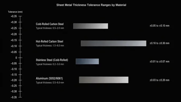
Typical thickness tolerance ranges vary significantly by material — cold-rolled carbon steel and aluminum hold tighter tolerances, while hot-rolled steel allows wider variation.
How to Specify Thickness Tolerance on Drawings
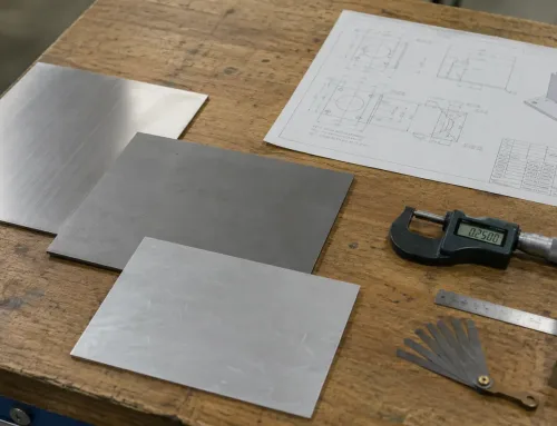
One of the most common sources of confusion between buyers and manufacturers is how sheet metal drawing requirements define thickness tolerance.
If your drawing does not explicitly state a thickness tolerance, the manufacturer will use the default from the material standard — which may or may not match what you need.
Default Tolerances in the Title Block
Most technical drawings include a general tolerance block that applies to all dimensions without specific callouts.
A typical entry might read: “Linear dimensions: ±0.2 mm (ISO 2768-m).”
This covers thickness along with all other linear dimensions. If the default tolerance is acceptable for your application, no additional annotation is needed.
When to Call Out Thickness Tolerance Explicitly
You need an explicit thickness callout when:
- The part must mate with another component where thickness directly affects fit (e.g., a slot or groove).
- The material will undergo surface treatment (anodizing, plating, powder coating) where thickness variation affects the final coating buildup.
- The part is used in a welded assembly where mismatch in thickness between mating parts causes weld defects.
- Your supplier uses a different material standard than what you assumed.
Drawing Callout Examples
A clear thickness callout on a drawing might look like:
Material: ASTM A1008 CS Type B, 1.5 mm ±0.05 mm
This tells the supplier the material, the nominal thickness, and the acceptable tolerance in a single line.
Without the ±0.05 mm callout, the supplier might apply the standard tolerance for that material and width, which could be ±0.08 mm or more.
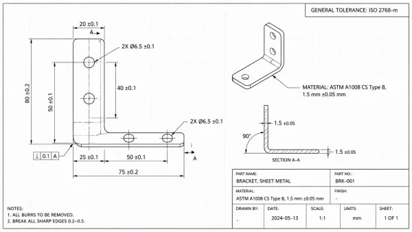
A clear drawing callout specifies the material standard, nominal thickness, and acceptable tolerance in a single line — removing ambiguity for the manufacturer.
What Happens When Thickness Is Out of Tolerance
Thickness tolerance is not just a number on a spec sheet. When actual material thickness falls outside the specified band, real manufacturing and assembly problems follow.
Assembly and Fit Issues
If a 2.0 mm sheet arrives at 2.15 mm — still within some standard tolerances but outside your design assumption — parts that were designed to slide into a 2.0 mm slot will not fit.
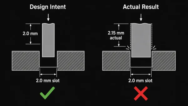
When actual sheet thickness exceeds the design assumption by even 0.15 mm, parts designed for a precise fit will no longer assemble correctly.
In assemblies with multiple stacked components, even a small per-part thickness error accumulates across the stack, creating dimensional mismatches that are difficult to correct after fabrication.
Welding and Joining Problems
When two sheets of different actual thickness are butt-welded, the mismatch creates an uneven joint. The thinner side penetrates more easily, while the thicker side may lack full fusion.
For lap joints, thickness variation changes the overlap contact area, which affects weld strength and consistency.
Bending and Forming Deviations
Sheet metal bending relies on the material’s actual thickness to calculate bend allowance and the K-factor.
If the incoming material is thicker or thinner than specified, the bend angle and flange length will deviate from the design intent. Over multiple bends in a single part, these deviations compound.
Verifying Incoming Material Thickness
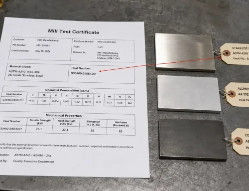
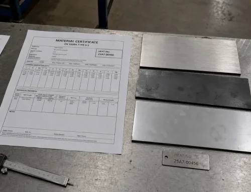
If your parts depend on a specific thickness, relying solely on the mill test report is not always sufficient.
Practical verification at incoming inspection helps catch material that is technically within the supplier’s tolerance but outside your design tolerance.
Measurement tools:
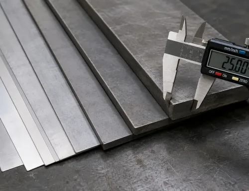
- A micrometer (resolution 0.001 mm) is the standard tool for sheet thickness measurement. Measure at least three points: near each edge and at the center.
- An ultrasonic thickness gauge is useful for coated or painted material where direct contact measurement would damage the surface.
Measurement locations:
Material thickness is rarely perfectly uniform across the sheet. Measure at multiple points — at least 25 mm from the edges and at the center — to capture the range.
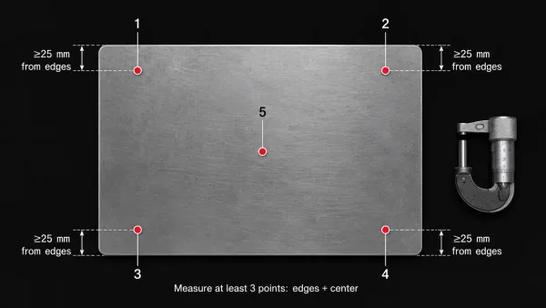
Measure thickness at multiple points across the sheet — at least 25 mm from each edge and at the center — to capture the full gauge variation range.
The thinnest and thickest readings within a single sheet define the gauge variation, which should stay within the specified tolerance band.
When to check every sheet versus sampling:
For critical applications (aerospace, medical, precision enclosures), measure every incoming sheet.
For general fabrication, a sampling plan — such as checking every fifth sheet or every coil — is usually sufficient. Document your sampling frequency in your incoming inspection procedure.
FAQs
The information in this article is intended for general engineering reference. Thickness tolerance values vary by material standard, mill capability, and order conditions. Always verify applicable tolerances against the specific material standard and your supplier’s certifications before finalizing design decisions.