Lap joints are everywhere in sheet metal fabrication. Enclosures, brackets, HVAC ducts, electrical housings — any assembly where two panels meet at an overlap relies on this joint type. Despite how common they are, poorly designed lap joints remain one of the top reasons for welding rework in sheet metal production. The difference between a joint that holds up and one that cracks, warps, or fails inspection usually comes down to decisions made at the sheet metal design stage, not the welding stage.
This guide covers the design parameters that matter most for sheet metal lap joints intended for welding: overlap dimensions, thickness matching, process selection, and the mistakes that drive up cost.
What Is a Sheet Metal Lap Joint?
A lap joint forms when two sheet metal pieces overlap and are joined by welding along the overlapping area. Unlike butt joints, where two edges meet flush, lap joints stack one sheet on top of the other. This makes them simpler to fit up — no need for precise edge alignment — and well suited to sheet metal where edge preparation is often impractical.
Plain Lap Joint vs. Flush Lap Joint
The plain lap joint is the most common configuration in sheet metal work. One sheet simply overlaps the other, and the weld is applied along the edge of the top sheet or across the overlap zone. It requires no special edge preparation and works with virtually any sheet thickness.
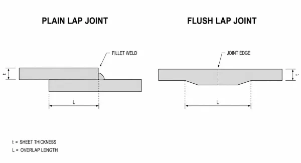
Cross-section comparison of a plain lap joint and a flush (scarf) lap joint, showing the difference in edge preparation and surface profile.
A flush lap joint (sometimes called a scarf lap) involves tapering or stepping the overlapping edges so the finished surface sits level. This is less common in standard sheet metal fabrication because it adds machining cost, but it matters in applications where a smooth exterior surface is required — aircraft panels, for example, or visible consumer product enclosures.
For most industrial sheet metal parts, the plain lap joint is the default. The design decisions that follow apply primarily to this configuration.
Why Lap Joint Design Matters for Sheet Metal Welding
A lap joint that looks simple on a drawing can produce surprisingly complex problems on the shop floor. Sheets that don’t fit tightly create gaps the weld can’t bridge cleanly. An overlap that’s too narrow leaves the joint weak under peel loading. A mismatch in sheet thickness causes the thin side to burn through while the thick side barely fuses.
These aren’t welding skill problems — they’re design problems. When the overlap is sized correctly, the sheets match in thickness, and the welding process is chosen with the joint geometry in mind, the weld itself becomes straightforward. When any of those factors are off, even an experienced welder will struggle to produce a consistent result.
Getting the design right on paper means fewer rejections, less rework, and parts that perform as intended in the field.
Overlap Dimensions: How Much Is Enough?
The overlap distance — the length by which the two sheets overlap — is the single most important dimension in a lap joint design. Too little overlap and the joint lacks strength, especially under peel or tensile loading. Too much and you’re adding material cost, weld length, and production time without proportional benefit.
Minimum Overlap Ratios by Material Thickness
A widely accepted engineering guideline is to set the overlap at 2 to 3 times the sheet metal thickness (2t–3t) for general-purpose applications. For a 1.0 mm steel sheet, that means a minimum overlap of 2.0 mm, with 3.0 mm providing a more comfortable margin.
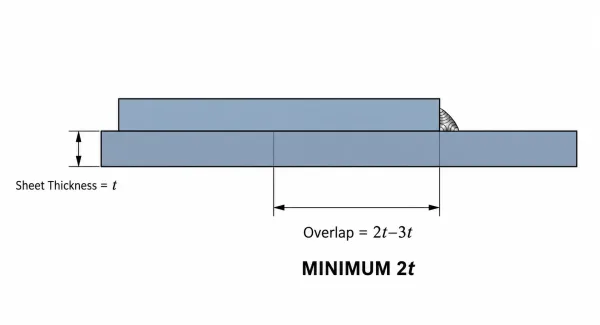
Dimensioned cross-section of a sheet metal lap joint illustrating the recommended 2t–3t overlap distance relative to sheet thickness.
For thicker structural plates (above 3 mm), overlap ratios of 3t–4t are common, particularly when the joint carries significant load. AWS D1.3 (Structural Welding Code — Sheet Steel) provides specific requirements for different thickness ranges and service conditions.
| Sheet Thickness | Minimum Overlap (General) | Recommended Overlap (Structural) |
|---|---|---|
| 0.5 mm | 1.0 mm | 1.5 mm |
| 1.0 mm | 2.0 mm | 3.0 mm |
| 1.5 mm | 3.0 mm | 4.5 mm |
| 2.0 mm | 4.0 mm | 6.0 mm |
| 3.0 mm | 6.0 mm | 9.0–12.0 mm |
When to Use Wider Overlap
Wider overlap is worth the extra material in three situations:
- Sealed joints — Continuous welds needed for gas or liquid tightness benefit from more overlap to ensure full penetration along the seam.
- High-stress locations — Joints in load-bearing brackets, frames, or mounting points should use the upper end of the 2t–3t range or beyond.
- Heat-sensitive materials — Aluminum and stainless steel dissipate heat differently than carbon steel. A wider overlap gives the welder more room to manage heat input without edge distortion.
Consistency matters as much as the dimension itself. If the overlap varies along the joint — because of poor bend accuracy or inconsistent part fit-up — the weld quality will vary with it.
Sheet Thickness Matching and Its Effect on Joint Quality
When two sheets of very different thicknesses are lapped, the welding process faces an inherent imbalance. The thinner sheet heats up faster, approaching its melting point while the thicker sheet is still absorbing energy. The result is predictable: burn-through on the thin side, incomplete fusion on the thick side.
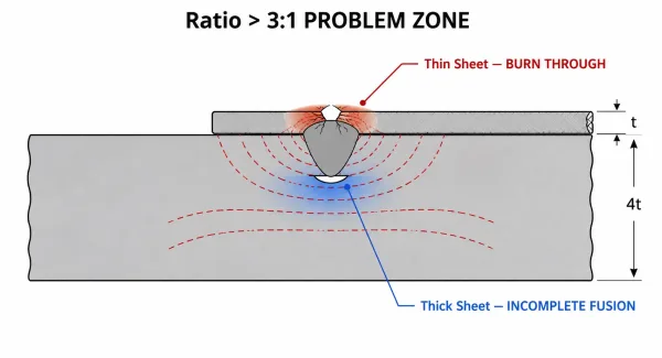
Cross-section illustrating burn-through on a thin sheet caused by a thickness ratio exceeding 3:1 during lap joint welding.
A practical rule of thumb is to keep the thickness ratio below 3:1. Pairing a 0.5 mm sheet with a 2.0 mm sheet (ratio of 4:1) is already in the problem zone. The thin sheet lacks the thermal mass to absorb the heat needed to fuse the thicker partner.
When a large thickness mismatch is unavoidable, several design adjustments can help:
- Use resistance spot welding — It delivers energy in short, controlled bursts rather than a continuous arc, reducing the risk of burning through the thin sheet.
- Offset the weld path — Shifting the weld slightly toward the thicker sheet directs more heat into the material that needs it.
- Consider a stepped lap — Adding a bend or step in the thicker sheet creates a more uniform cross-section at the weld zone.
The key point for designers is that thickness matching is not just a sheet metal material selection issue. It directly determines whether the joint can be welded consistently at production scale.
Choosing a Welding Process for Lap Joints
The three most common sheet metal welding processes for lap joints — MIG, TIG, and resistance spot welding — each impose different design requirements. Selecting the process at the design stage, not the shop floor, ensures the joint geometry supports the chosen method.
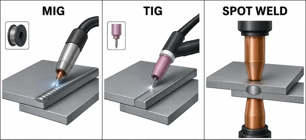
Visual comparison of MIG, TIG, and resistance spot welding applied to sheet metal lap joints, showing weld appearance and equipment access.
MIG Welding Lap Joints
MIG (GMAW) is the most widely used process for steel and stainless steel lap joints in general fabrication. It offers a good balance of speed and versatility across sheet thicknesses from about 0.8 mm upward.
For lap joints, MIG works well with a fillet weld along the edge of the top sheet. Design considerations include ensuring adequate access for the welding gun — tight corners or deep recesses can block the contact tip-to-work distance — and accounting for the slight gap that the wire feed creates between sheets.
TIG Welding Lap Joints
TIG (GTAW) provides finer control over heat input, making it the preferred choice for thin aluminum, stainless steel, and any application where weld appearance matters. It is slower and more expensive than MIG, but produces cleaner, more precise welds on sheet metal.
On lap joints, TIG allows the operator to direct heat precisely into the overlap zone, which is an advantage when working with dissimilar thicknesses or heat-sensitive alloys. The tradeoff is speed — TIG lap welds on production runs take significantly longer than MIG or spot welding.
Resistance Spot Welding Lap Joints
Spot welding is the standard process for high-volume sheet metal assembly — automotive body panels, appliance housings, and electrical enclosures. It requires no filler metal, produces minimal distortion, and completes each weld in under a second.
The design requirements are specific: the overlap must be wide enough to accommodate the electrode tip diameter plus edge margin (typically 1.5× electrode diameter minimum), and the sheets must be held in tight contact during welding. Spot welding also requires both sides of the joint to be accessible — a constraint that rules out some enclosed geometries.
| Factor | MIG | TIG | Spot Welding |
|---|---|---|---|
| Speed | Moderate | Slow | Fast |
| Precision | Moderate | High | Moderate |
| Filler metal | Yes | Yes | No |
| Typical use | General fabrication | Thin/exotic metals, visible welds | High-volume assembly |
| Min. sheet thickness | ~0.8 mm | ~0.5 mm | ~0.4 mm (with appropriate equipment) |
| Access requirement | One side | One side | Both sides |
Common Lap Joint Design Mistakes and How to Avoid Them
Most lap joint welding problems trace back to a handful of design-level errors. Fixing them in the drawing is far cheaper than fixing them after welding.

Four common design mistakes in sheet metal lap joints: insufficient overlap, excessive thickness mismatch, uncontrolled gap between sheets, and free-edge distortion.
Insufficient overlap. The most frequent mistake. A narrow overlap reduces the joint’s load-carrying area and makes it vulnerable to peel failure. For general sheet metal work, maintain at least 2t overlap; for structural applications, go to 3t or more.
Excessive thickness mismatch. Pairing sheets with a ratio beyond 3:1 creates an uneven heat balance. The thin sheet burns through before the thick sheet reaches fusion temperature. When the application demands a mismatch, switch to spot welding or redesign the joint as a stepped lap.
Uncontrolled gap between sheets. A gap wider than 0.5 mm between the overlapping sheets causes porosity, incomplete fusion, and inconsistent weld profiles. This is usually a fit-up problem rooted in sheet metal bending accuracy, because inconsistent bend angles can change the overlap gap along the joint. Specifying tighter bend tolerances or adding locating features (tabs, slots, or pilot holes) to the design keeps the gap under control.
Ignoring distortion. Lap joints tend to curl upward at the free edge during welding due to differential thermal expansion. On long seams in thin material, this distortion can be significant. Designing in tack weld points at regular intervals, or adding a slight pre-bend in the opposite direction, counteracts the effect.
Mismatching weld type to sealing requirement. Spot welds are efficient but not inherently sealed. If the joint must be gas- or liquid-tight, a continuous weld is required — and that changes the cost equation entirely. Defining the sealing requirement on the drawing prevents the fabricator from guessing.
Balancing Strength, Cost, and Manufacturability
Every millimeter of overlap adds material, weld length, and processing time. The right lap joint design matches the joint’s actual function — not every joint needs maximum strength.
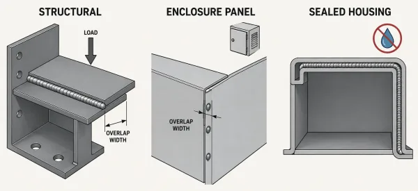
Three application categories for sheet metal lap joints — structural, enclosure panel, and sealed housing — each with different overlap and weld requirements.
- Structural joints (brackets, frames, load-bearing panels) warrant the upper end of the overlap range and continuous or closely spaced welds. The extra cost is justified by the performance requirement.
- Enclosure panels and covers can often use smaller overlaps with spot welds. The joint needs to hold the parts together, not carry significant load.
- Sealed housings need continuous welds but don’t necessarily need excessive overlap. A 2t overlap with a full-penetration weld is usually sufficient for gas tightness.
The principle is straightforward: design the joint for what the part needs to do. Every unnecessary millimeter of overlap or extra weld pass adds cost without adding value.
Key Takeaways
When designing sheet metal lap joints for welding, three factors determine both joint quality and manufacturing cost: overlap distance (2t–3t as a baseline), thickness matching (keep the ratio below 3:1), and welding process selection (match the process to the geometry and production volume). Addressing these at the design stage prevents the most common — and most expensive — welding problems.
FAQs
Have a sheet metal design with lap joints you’d like reviewed? Submit your drawings to SR-MFG for a design-for-manufacturing assessment and a fast, competitive fabrication quote. Our engineering team can identify potential welding issues before production begins — saving you time and rework cost.