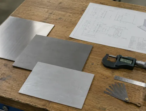
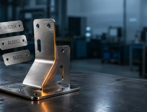
Ask a fabricator for “16 gauge”, and the actual thickness will vary depending on whether the material is steel, aluminum, or stainless steel.
That single fact explains the main problem with the gauge system: it was never designed to be precise. Using a gauge number without an actual thickness is one of the easiest ways to introduce errors into a project.
Sheet thickness is one of the first dimensions specified on a sheet metal drawing, yet one of the last to be questioned. It affects nearly every downstream decision, from tooling and processing to the final cost of the part.
What Sheet Thickness Actually Means in Fabrication
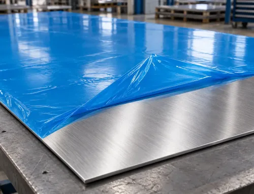
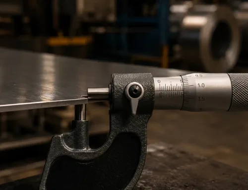
In sheet metal fabrication, thickness is the distance between the two flat surfaces of a metal sheet, measured under a standardized static load.
It is not necessarily identical to the nominal value on a purchase order. Real sheets have a tolerance range, so the measured thickness may be slightly above or below the value shown on the drawing.
Sheet vs. Plate vs. Foil
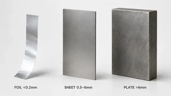
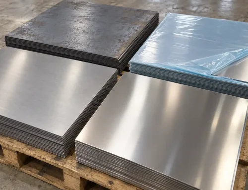
Three metal pieces representing the industry’s informal thickness categories — foil, sheet, and plate — each standing upright to show their relative thickness and rigidity.
The industry uses informal thickness-based categories:
- Foil: Thinner than 0.2 mm (0.008 in.) and unable to hold its shape without support.
- Sheet: Typically 0.5–6.0 mm (0.020–0.236 in.) and commonly used for laser cutting, bending, and stamping.
- Plate: Thicker than 6.0 mm and usually processed with different equipment.
Most fabrication work falls within the sheet range, although the exact boundaries vary by region and material.
One shop may call 6 mm steel “heavy sheet,” while another treats it as plate. The classification matters less than specifying the actual thickness in millimeters or inches.
The Gauge System: Why Smaller Numbers Mean Thicker Metal
The gauge system works backward:
The lower the gauge number, the thicker the metal.
For example, 10-gauge steel is approximately 3.42 mm thick, while 16-gauge steel is approximately 1.52 mm thick.
How Gauge Numbers Were Derived
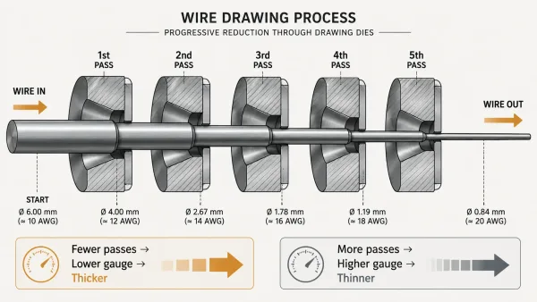
A diagram illustrating how the gauge numbering system originated from wire drawing, where more passes through smaller dies produced thinner wire with a higher gauge number.
The gauge scale originated in the wire-drawing industry. Wire was pulled through progressively smaller dies, with each pass reducing its diameter.
More passes produced thinner wire and a higher gauge number. The same numbering convention was later applied to flat sheet, even though sheets are rolled rather than drawn.
The system was never unified across sheet metal materials. Steel, stainless steel, aluminum, and galvanized steel use different gauge-to-thickness tables.
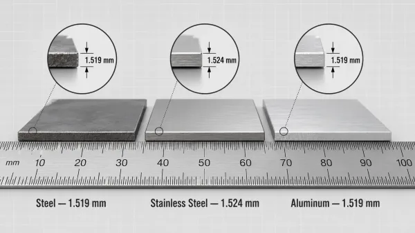
Three cross-sectional views of 16-gauge metal strips in steel, stainless steel, and aluminum, with magnified callouts revealing the small but real thickness differences between materials at the same gauge number.
For example:
- 16-gauge steel: 1.519 mm
- 16-gauge aluminum: 1.519 mm
- 16-gauge stainless steel: 1.524 mm
The differences are small, but they exist and may accumulate in assemblies containing multiple materials.
Gauge-to-mm Quick Reference
| Gauge | Steel (mm) | Stainless Steel (mm) | Aluminum (mm) |
|---|---|---|---|
| 10 | 3.416 | 3.571 | 3.416 |
| 12 | 2.657 | 2.642 | 2.657 |
| 14 | 1.897 | 1.893 | 1.897 |
| 16 | 1.519 | 1.524 | 1.519 |
| 18 | 1.214 | 1.219 | 1.214 |
| 20 | 0.914 | 0.914 | 0.914 |
| 22 | 0.762 | 0.762 | 0.762 |
| 24 | 0.610 | 0.610 | 0.610 |
For a complete conversion table, use Xometry’s gauge converter or a similar online tool. The table above covers the gauges most commonly encountered in B2B fabrication.
A drawing marked only “16 GA” without a complete sheet metal material specification is incomplete. The fabricator must guess which conversion table applies, and guessing can result in incorrect parts.
How Thickness Affects Manufacturing
Thickness is more than a drawing value. It is a constraint that affects every fabrication stage.
Designers who understand these effects make better decisions. Those who do not may need to revise the design after the first sample run.
Bending: Radius, Force, and Springback
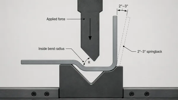
An annotated cross-section of a press brake bending operation, highlighting the inside bend radius, applied force, and the springback effect that causes the material to partially unbend after pressure is released.
In sheet metal bending, thicker sheets require more bending force.
A press brake that easily bends 1 mm aluminum may struggle with 3 mm steel using the same die.
The minimum achievable inside bend radius also increases with thickness. A common rule of thumb is:
- Steel: Inside radius of at least 1× material thickness
- Aluminum: Inside radius of at least 1.5× material thickness to avoid cracking
Springback increases with material thickness and strength.
Thin mild steel may require little overbending, while thick stainless steel can spring back 2°–3° and require compensation in the press brake program.
Laser Cutting: Speed, Edge Quality, and Gas Pressure
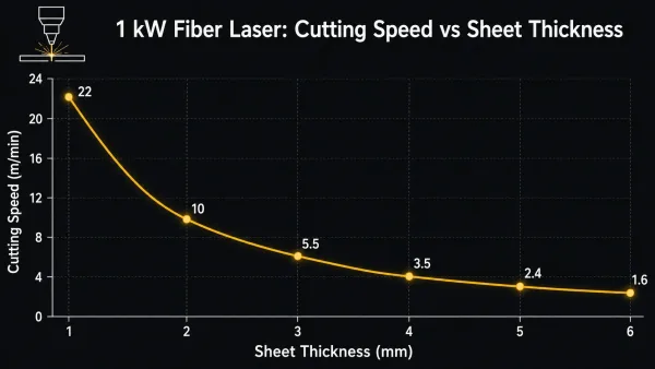
A chart illustrating the dramatic drop in laser cutting speed as material thickness increases, based on a 1kW fiber laser cutting steel — from over 20 m/min at 1mm to under 2 m/min at 6mm.
Cutting speed drops sharply as thickness increases.
A 1 kW fiber laser may cut 1 mm steel at more than 20 m/min, but slow to less than 2 m/min when cutting 6 mm of the same material.
Assist gas pressure—typically oxygen or nitrogen—must increase to remove molten material from the kerf. Edge quality, including surface roughness and dross formation, also becomes harder to control.
Near the upper limit of a laser’s thickness capacity, cost per cut meter rises faster than thickness alone would suggest. This is one reason some shops switch to plasma or waterjet cutting above certain thresholds.
Welding: Heat Input and Distortion
Thicker material requires more heat input for full penetration, and more heat increases distortion risk.
A 1 mm enclosure panel may need only spot welds or short stitch welds. A 4 mm structural bracket may require continuous welds and carefully planned sequencing to prevent warping.
Joint preparation also changes with thickness. Sheets above approximately 3 mm often require beveling or V-groove preparation to ensure root penetration, adding time and cost.
Thickness Tolerance: What the Drawing Does Not Tell You
A nominal 2 mm sheet is not exactly 2.000 mm everywhere.
Steel mills supply sheet according to defined sheet metal thickness tolerance ranges under applicable material standards. These ranges may be wider than designers expect.
Mill Tolerance vs. Fabrication Tolerance
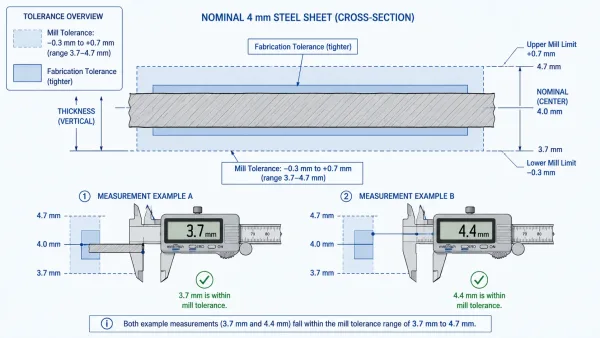
A cross-sectional view of a 4mm nominal steel sheet showing the wide mill tolerance range (3.7–4.7mm) compared to the tighter fabrication tolerance, with actual measured thickness points illustrating how real sheets vary within specification.
Two types of tolerance are involved:
- Mill tolerance: The permitted variation in raw sheet thickness, controlled by the rolling mill. For cold-rolled steel with a nominal thickness between 3 mm and 5 mm, the permitted range may be −0.3 mm to +0.7 mm. A nominal 4 mm sheet could therefore measure 3.7 mm and remain within specification.
- Fabrication tolerance: The dimensional accuracy achieved during cutting, bending, and punching. This is controlled by the fabrication shop and is usually tighter than mill tolerance.
This distinction matters because bend angle, flange length, and flatness depend on the material’s actual thickness at the bend.
A sheet near the lower end of the mill tolerance may produce a slightly more open bend. A sheet near the upper end may prevent the part from fitting the intended assembly.
ISO 16162 / EN 10029 Thickness Tolerance Ranges
| Nominal Thickness (mm) | Tolerance (mm) |
|---|---|
| 0.5–1.0 | ±0.07 |
| 1.0–2.0 | ±0.09 |
| 2.0–3.0 | ±0.11 |
| 3.0–5.0 | −0.3 / +0.7 |
| 5.0–8.0 | −0.3 / +0.8 |
These values apply to cold-rolled steel under EN 10131. Hot-rolled steel and other materials have different tolerance ranges.
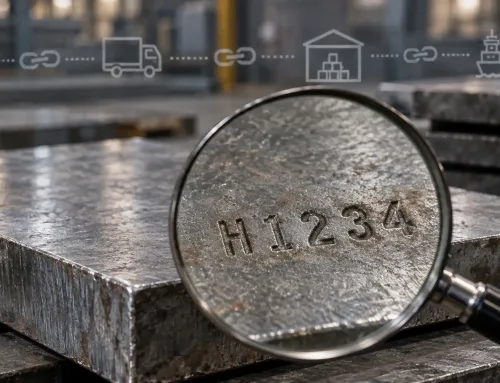
When uncertain, ask the fabricator what tolerances they typically receive from their material suppliers. Actual variation depends on the mill and region.
How to Specify Thickness on Drawings
Correctly specifying sheet thickness is straightforward, but several common mistakes create real production problems.
Specify Millimeters or Inches, Not Gauge Alone
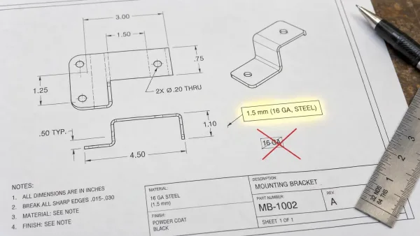
A detail from an engineering drawing comparing a proper thickness callout (“1.5 mm (16 GA, STEEL)”) with an incomplete callout (“16 GA” only), illustrating the best practice of always specifying actual thickness alongside gauge number.
Always state the actual thickness in millimeters or inches.
A note marked only “16 GA” forces the shop to find the conversion. If the material is not specified, the wrong table may be used.
Use an unambiguous callout such as:
1.5 mm (16 GA, steel)
Apply Tight Tolerances Only Where Necessary
Only specify a thickness tolerance when the application requires it.
Most fabrication work performs adequately under standard mill tolerance. Specifying ±0.05 mm for a bracket with 1 mm of clearance means paying for precision the part does not need.
A tighter tolerance may be justified where mating surfaces must fit closely, including:
- Gasket grooves
- Sliding rails
- Press-fit pockets
In these cases, explicitly stating the tolerance prevents the shop from relying only on the mill specification.
Expect Higher Costs for Non-Standard Thicknesses
Non-standard thicknesses usually increase lead time and cost.
Common stock thicknesses include:
- 0.8 mm
- 1.0 mm
- 1.2 mm
- 1.5 mm
- 2.0 mm
- 2.5 mm
- 3.0 mm
These sizes are normally available from steel service centers.
A drawing specifying 1.8 mm may require the supplier to source a specialty run or order material directly from a mill. Either option adds time and cost.
Consult the Fabricator Before Finalizing the Drawing
If you are unsure which thickness to use, confirm it with the fabricator during the sheet metal design stage before releasing the drawing.
A brief discussion at this stage avoids later substitutions, deviation approvals, and repeated revisions.