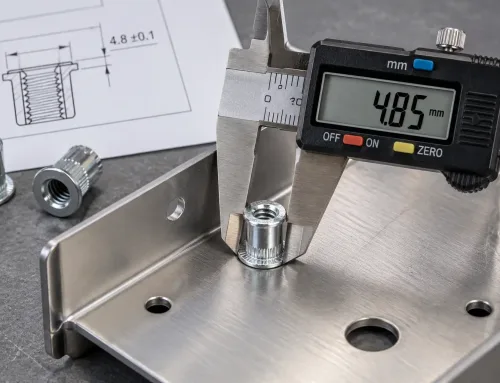
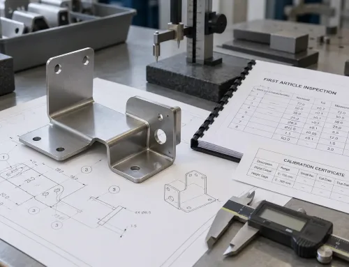
A gasket is seated, the bolts are torqued, and the flange gap looks even. The assembly moves to shipping — or does it? On a sheet metal enclosure, a fabricated bracket, or a welded housing, the difference between a sealed joint and a field leak often comes down to what happens in the few minutes after the gasket goes in. This guide walks through a systematic sheet metal inspection workflow, from pre-installation checks through post-installation verification, with acceptance criteria you can put on a checklist.
What to Check Before the Gasket Goes In
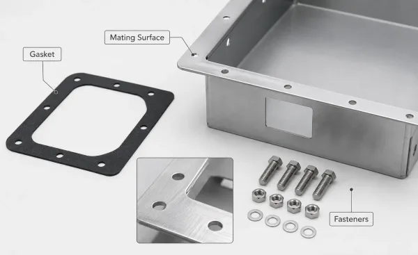
Inspection of the gasket, mating surface and hardware before assembly.
Most gasket failures trace back to conditions that existed before the first bolt was tightened. Pre-installation inspection confirms that the gasket, the mating surfaces, and the fasteners are all fit for the job.
Gasket Identity and Condition
Start with the gasket itself. Verify that the part number, material, and dimensions match the drawing specification. A common error on the shop floor is grabbing a gasket that is close in size but wrong in material — an EPDM gasket where a silicone one was specified, for example, or a 2 mm thickness where the callout reads 1.5 mm.
Check that the gasket is new and unused. Reusing a gasket that has already taken a compression set is one of the most reliable ways to create a leak path, because the material no longer has the elastic recovery needed to conform to surface irregularities.
Inspect the gasket surface under adequate lighting. Look for cuts, nicks, delamination, or contamination from oil, dirt, or metal shavings. For die-cut sheet gaskets, check that the inner and outer edges are clean and free of burrs that could prevent uniform compression. For O-rings or molded seals, check for parting-line flash or mold defects that compromise the cross-section.
Mating Surface Quality
The flange or mating surface on the sheet metal part must be clean, flat, and free of defects that create leak paths. Remove all old gasket material, weld spatter, paint overspray, and burrs from stamping or laser cutting.
On sheet metal parts, pay particular attention to edges near cutouts and holes — burrs and dross on sheet metal edges can prevent the gasket from seating flush.
Check flatness with a straightedge and feeler gauge.
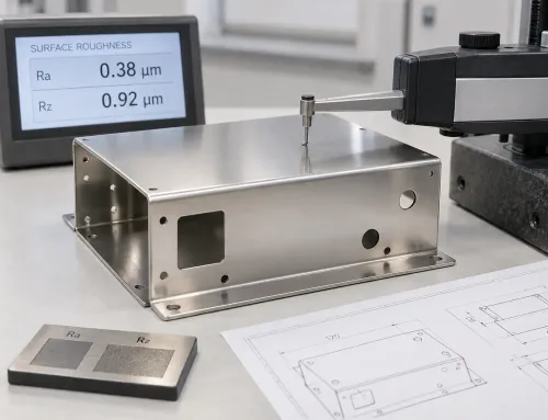
For soft gaskets (compressed fiber, PTFE, rubber), a surface roughness of Ra 3.2–6.3 µm (125–250 µin) is typically acceptable.
For metallic or semi-metallic gaskets, the requirement tightens to Ra 1.6–3.2 µm (63–125 µin).
If the drawing specifies a surface finish, measure it — do not assume the machining or forming step delivered it.
Fastener and Hardware Readiness
Inspect bolts, nuts, and washers before installation. Threads must be clean, undamaged, and free of burrs. Nuts should run freely along the full bolt length by hand.
Damaged or corroded fasteners do not distribute load evenly and are a direct cause of uneven gasket compression.
Verify that the fastener grade and length match the drawing. Using a bolt that is too short reduces thread engagement; using one that is too long bottoms out before achieving the target gasket stress.
Verifying the Installation in Progress
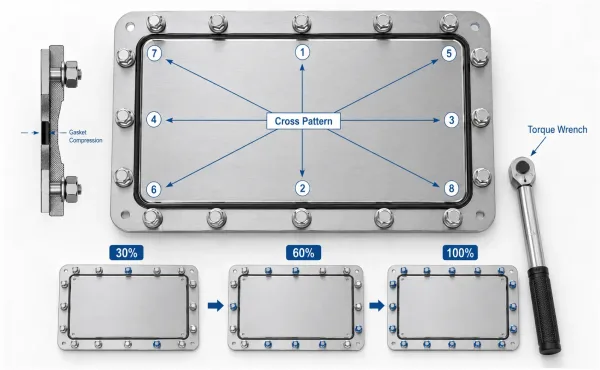
A bolted gasket joint showing the correct cross-pattern tightening sequence and staged torque approach.
Inspection does not pause once the gasket is placed. The installation steps themselves are verification points.
Alignment and Centering
Once the gasket is positioned on the lower flange, confirm it is centered. The gasket should sit within the bolt circle without extending into the bore or overhanging the outer edge.
On sheet metal assemblies with irregular flange shapes, use alignment pins or locating features to prevent the gasket from shifting when the mating part is lowered into position.
A gasket that migrates during assembly may seat off-center, creating an uneven stress distribution that does not show up until pressure testing — or until the part is in the field.
Bolt Tightening Sequence and Torque
Tighten bolts in a cross pattern, not in a circle. A circular sequence biases the gasket toward one side, producing uneven compression.
The standard practice is a minimum of three passes:
- Pass 1: Hand-tighten all bolts to seat the gasket.
- Pass 2: Torque each bolt to approximately 30 % of the target value, following the cross pattern.
- Pass 3: Torque to 60 %, then to 100 %, repeating the cross pattern at each stage.
Use a calibrated torque wrench — not an impact gun.
The target torque value comes from the gasket manufacturer’s data or the engineering specification, not from shop-floor habit.
After the final pass, make one clockwise rotation bolt-by-bolt to confirm uniform load.
On a sheet metal flange that is thinner and less rigid than a pipe flange, over-torquing is as dangerous as under-torquing: it warps the flange, crushes the gasket, and creates the very leak path the gasket was meant to prevent.
Post-Installation Inspection Checklist
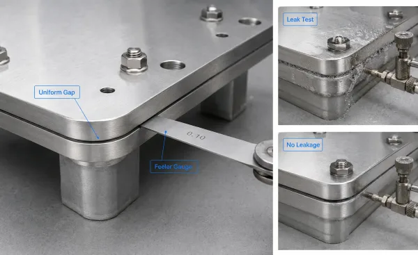
Visual gap inspection and leak testing after gasket installation on a sheet metal assembly.
With the gasket installed and the bolts torqued, the assembly is ready for pre-shipment inspection. This is the point where you confirm that the installation actually produced a sealed joint.
Visual and Dimensional Checks
Start with a visual sweep. The gasket should not be visible from the outside — if you can see gasket material protruding from the joint, it is either misaligned, over-compressed, or the wrong size.
Check that the flange gap is uniform around the entire perimeter.
Use a feeler gauge at four or more points. On a sheet metal assembly, a gap variation greater than 0.3 mm (0.012 in.) across the joint suggests uneven bolt load or a warped flange that needs correction.
Look for signs of gasket extrusion — material squeezed out of the joint — and for any visible damage to the flange edge that occurred during assembly.
Leak and Pressure Testing
For assemblies that must hold pressure, a leak test is the definitive check. The method depends on the application:
- Air pressure test: Pressurize the assembly to the specified test pressure (commonly 1.5 × working pressure) and hold for a defined duration. Apply a soap solution to the joint and watch for bubbles.
- Water immersion test: Submerge the pressurized assembly and look for streams of bubbles.
- Vacuum test: For low-pressure or non-pressurized assemblies, draw a vacuum on the sealed volume and monitor for pressure rise over time.
Record the test pressure, hold time, and result.
A pass means no visible leakage at the specified pressure and duration. Any seepage, weeping, or bubble formation is a fail — do not accept “minor” leaks on the assumption that they will seal under operating conditions.
Torque Retention Check
Gaskets relax after installation. Bolt load drops as the gasket material creeps and as thermal cycles introduce stress relaxation.
For critical assemblies, re-torque the bolts after 4–24 hours at ambient temperature, following the same cross pattern.
Measure and record the torque on each bolt before and after re-torque.
If the re-torque value is more than 20 % below the original target, investigate the cause — it may indicate gasket creep, bolt yield, or a flange that was not flat to begin with.
Acceptance Criteria — What “Pass” and “Fail” Actually Look Like
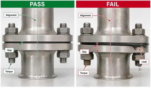
Comparison of acceptable and unacceptable gasket installation conditions on a sheet metal joint.
Inspection without a standard is just observation.
The table below provides reference manufacturing acceptance criteria for sheet metal gasket joints. Adjust values to match the specific gasket manufacturer’s data and the drawing requirements.
| Check Item | Pass | Fail | Reference |
|---|---|---|---|
| Gasket alignment | Centered within bolt circle, no protrusion | Visible offset or material extending into bore | Visual / straightedge |
| Flange gap uniformity | ≤ 0.3 mm (0.012 in.) variation around perimeter | > 0.3 mm variation | Feeler gauge, ≥ 4 points |
| Surface finish (flange) | Ra 3.2–6.3 µm for soft gaskets; Ra 1.6–3.2 µm for metallic | Exceeds specified Ra | Surface profilometer |
| Torque deviation | ±10 % of target value on all bolts | Any bolt outside ±10 % | Calibrated torque wrench |
| Re-torque retention | Re-torque value within 20 % of original target | > 20 % drop | Torque wrench, 4–24 h post-install |
| Pressure test | No leakage at specified test pressure and hold time | Any visible seepage or bubble formation | Pressure gauge, soap solution |
| Visual defects | No extrusion, cuts, or damage visible at joint | Extruded material, visible gasket damage | Visual inspection |
These criteria are a starting point. The drawing or the gasket manufacturer may specify tighter or looser limits depending on the application — always defer to the engineering specification when a conflict exists.
Sample-Stage vs. Production-Stage Inspection
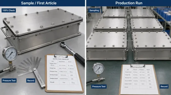
Comparison between first-article gasket inspection and production-run inspection for sheet metal assemblies.
The inspection approach changes depending on whether you are validating a first article or running a production batch. The table below summarizes the key differences.
| Dimension | Sample / First Article | Production Run |
|---|---|---|
| Purpose | Prove the design works — verify compression, sealing, and assembly fit | Prove consistency — every unit meets the same standard |
| Torque check | 100 % of bolts, recorded individually | Statistical sampling (e.g., first-off, last-off, random intervals) |
| Pressure test | Every assembly | Sampling plan per AQL or 100 % for critical applications |
| Dimensional check | Full flange gap measurement at ≥ 4 points | Spot checks at defined frequency |
| Surface finish | Measured and recorded on the mating surface | Verified at process setup; spot-check if tooling changes |
| Re-torque verification | Performed and documented | Performed on first article; production frequency per process validation |
| Record retention | Full inspection report with data, photos, and pass/fail | Retained per quality system requirements (often 5–10 years for aerospace or medical) |
At the sample stage, the goal is to confirm that the design — flange flatness, gasket selection, bolt pattern, torque specification — actually produces a sealed joint under the expected conditions.
Every variable is measured and recorded because you are building the baseline.
In production, the goal shifts to consistency. You already know the design works; now you need to verify that every assembly coming off the line meets the same standard.
This means defined inspection frequency, calibrated tools, and a clear escalation path when a check fails. The inspection record becomes the evidence that the process is under control, not just a one-time pass.
Common Inspection Gaps That Cause Field Failures
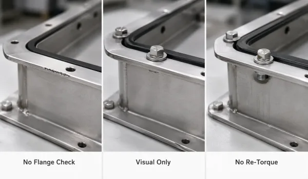
Three common inspection mistakes that can lead to gasket sealing failures.
Even well-intentioned inspection programs have blind spots. The three gaps below account for a disproportionate share of field failures.
Skipping Pre-Installation Flange Checks
The most common shortcut is inspecting the gasket but not the surface it seats against.
A gasket that meets every specification will still leak if the flange has a burr from laser cutting, a low spot from welding distortion, or residual sealant from a previous assembly.
On sheet metal parts, flange flatness is particularly sensitive to forming tolerances and weld heat input — check it, do not assume it.
Relying Only on Visual Inspection
A joint that looks sealed may not be sealed.
Visual inspection catches gross errors — a misaligned gasket, visible extrusion, a missing bolt — but it does not detect inadequate bolt load, subsurface gasket damage, or micro-leak paths.
For any assembly that must hold pressure or maintain a seal under vibration or thermal cycling, a pressure test or functional test is not optional.
Ignoring Re-Torque Requirements
Bolt load drops after installation. This is not a defect — it is a property of the joint.
Gasket materials creep, bolt threads settle, and flange surfaces conform under load.
Skipping the re-torque step means accepting whatever residual bolt load remains after relaxation, which may be below the minimum required for a reliable seal.
For high-temperature or cyclic applications, re-torque is not a courtesy — it is a requirement.