Acceptance criteria are the pre-established, measurable conditions that a manufactured part must satisfy before it is approved for shipment. They translate a part’s design intent into concrete pass/fail rules that inspectors apply at defined checkpoints — turning subjective judgment calls into objective, documented decisions.
What Are Acceptance Criteria?
In manufacturing, acceptance criteria define what “good enough” looks like for a specific part. They are not the same as specifications. A specification describes what a part should be — its dimensions, material, and finish. Acceptance criteria describe how to determine whether the part actually meets that specification — which measurements to take, what inspection methods and instruments to use, and what range of values is acceptable.
For example, a specification might call for a hole diameter of 10 mm. The acceptance criteria would specify that the measured diameter must fall between 9.95 mm and 10.05 mm, measured with a pin gauge or coordinate measuring machine (CMM), at a defined inspection frequency.
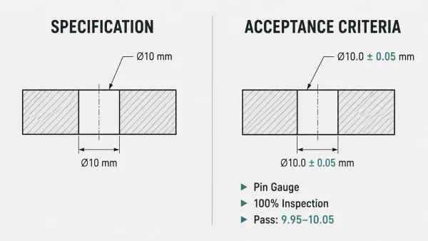
A side-by-side technical diagram illustrating the difference between a specification (“hole diameter 10 mm”) and its corresponding acceptance criteria (“10.0 ± 0.05 mm, pin gauge, 100% inspection”), showing how each is documented on a drawing.
This distinction matters because specifications without acceptance criteria leave room for interpretation. When a buyer and a manufacturer disagree on whether a part is acceptable, the root cause is almost always a gap between what was specified and what was actually defined as passable.
Attribute Criteria vs. Variable Criteria
Manufacturing acceptance criteria fall into two categories, and the type you choose affects how parts are inspected and what statistical confidence is needed.
Attribute criteria produce a binary result — conforming or nonconforming, pass or fail. They apply to characteristics that cannot be meaningfully measured on a continuous scale. Examples include surface finish classification (smooth vs. textured), label presence, or whether a weld bead is continuous or intermittent. An inspector classifies each unit against a defined standard without recording a numerical value.
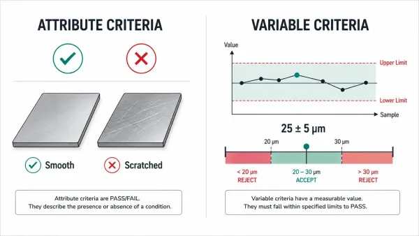
A technical comparison diagram showing attribute criteria (binary pass/fail decision) on the left and variable criteria (numerical measurement against a tolerance range) on the right, with representative examples for each type.
Variable criteria produce a measured number that is compared against a specification range. Dimensional tolerances (±0.1 mm), hardness values (HRC 58–62), and coating thickness (25 ± 5 μm) are all variable criteria. Because variable data can be analyzed statistically, it allows the use of process capability indices (Cpk) and sampling plans that reduce inspection cost while maintaining confidence in lot quality.
Most sheet metal parts require a mix of both types. Hole diameters and bend angles are typically controlled by variable criteria, while visual defects (scratches, dents, discoloration) are judged by attribute criteria.
Where Acceptance Criteria Come From
Acceptance criteria do not appear out of thin air. They originate from three sources, and a well-prepared drawing will reference all that apply.
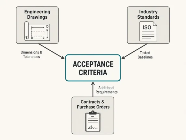
A structured diagram illustrating the three origins of acceptance criteria in manufacturing — engineering drawings, industry standards, and contracts/purchase orders — each connected to a central “Acceptance Criteria” block.
Engineering drawings are the primary source. When an engineer specifies a dimension with a tolerance — say, 50.0 ± 0.2 mm — that tolerance is an acceptance criterion. The drawing’s title block often defines default tolerances for dimensions without explicit values, and notes may reference specific inspection methods or standards.
Industry standards provide tested baselines that both buyer and manufacturer can reference. Common standards include ISO 2768 for general tolerances, ASTM A36 for carbon steel mechanical properties, ISO 5817 for weld quality levels, and ASTM B117 for salt spray corrosion testing. Referencing a standard on the drawing eliminates ambiguity — both parties know exactly what “acceptable” means.
Contracts and purchase orders sometimes add requirements beyond what the drawing specifies. A buyer might require a first article inspection (FAI) report, specific packaging methods, or a tighter tolerance than the standard allows. These contractual requirements become part of the acceptance criteria and should be documented alongside the drawing to avoid confusion during production.
What Acceptance Criteria Cover in Sheet Metal Parts
For buyers and engineers sourcing custom sheet metal fabrication, acceptance criteria typically span five dimensions. Understanding what each covers helps ensure nothing critical is left undefined on the drawing.
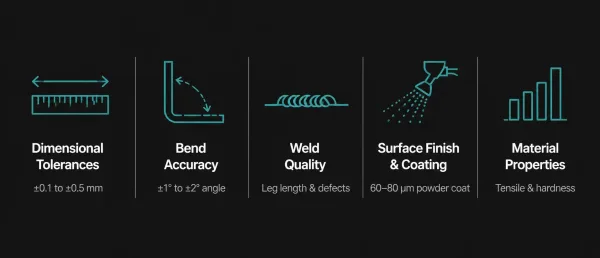
A structured infographic presenting the five key dimensions of acceptance criteria for fabricated sheet metal parts, each with a representative icon and brief descriptor.
Dimensional tolerances control linear dimensions (length, width, height), hole positions and diameters, and cutout profiles. For sheet metal parts made by laser cutting or punching, dimensional tolerances of ±0.1 mm to ±0.5 mm are common, depending on the process and material thickness.
Bend accuracy includes bend angle (typically ±1° to ±2°), bend radius, and the resulting flange length. Bending tolerances are influenced by material type, thickness, and the bending method (air bending, bottoming, or coining). A bend that is even slightly off can cause assembly interference or weaken the part.
Weld quality is defined by weld size (leg length, throat thickness), appearance (uniformity, spatter), and allowable defects (porosity, undercut, incomplete fusion). Standards such as AWS D1.1 (structural steel) or ISO 5817 (fusion welding) classify weld quality into levels — and the drawing should specify which level applies.
Surface finish and coating requirements cover coating type and thickness (e.g., powder coating at 60–80 μm), adhesion (measured by cross-hatch test per ASTM D3359), color matching, and corrosion resistance (often validated by salt spray testing per ASTM B117). For parts that require specific surface roughness, Ra values (e.g., Ra 0.8 μm) should be called out on the drawing.
Material properties include chemical composition and mechanical properties such as tensile strength, yield strength, and hardness. These are typically verified through mill test certificates provided by the material supplier, and the drawing should reference the applicable material standard (e.g., ASTM A240 for stainless steel, EN 10025 for structural steel).
When Acceptance Criteria Are Missing or Unclear
The most expensive problems in custom part procurement rarely come from poor manufacturing — they come from unclear expectations. When a drawing does not define acceptance criteria, the manufacturer must fall back on industry norms or internal manufacturing quality requirements. These defaults are often reasonable, but they are not guaranteed to match what the buyer has in mind.
The consequences are predictable. Parts are produced, shipped, and then rejected during incoming inspection because the buyer expected a tighter tolerance, a different surface finish, or a specific inspection method that was never communicated. The result is a cycle of rework requests, delivery delays, and cost overruns that could have been avoided with a few lines on the drawing.
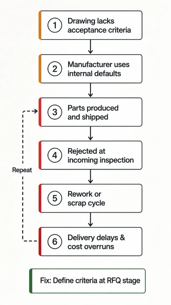
A flowchart illustrating the negative cycle that occurs when acceptance criteria are undefined on a drawing, from unclear specifications through manufacturing defaults, shipment, incoming inspection rejection, rework, and delivery delays.
This is especially true for low-volume or prototype sheet metal projects, where the cost of a single reworked batch can exceed the original order value. Investing time in defining acceptance criteria before the RFQ stage — not after the parts arrive — is one of the most effective ways to reduce procurement risk.
How to Specify Acceptance Criteria on Your Drawings
If your drawing currently relies on general notes like “parts must meet quality standards,” it is not providing enough information. Here are five steps to make your acceptance criteria actionable.
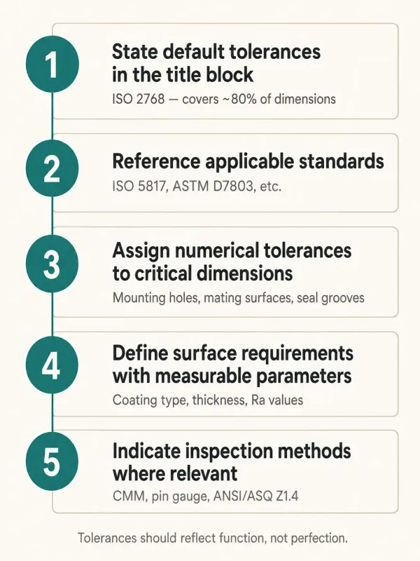
A five-step visual guide illustrating how to specify acceptance criteria on engineering drawings, from defining title block tolerances to indicating inspection methods.
State default tolerances in the title block. Define the tolerance band for dimensions that do not carry individual annotations. Common choices follow ISO 2768 (fine or medium class) or a company-specific standard. This single step eliminates ambiguity for roughly 80% of dimensions on a typical sheet metal drawing.
Reference applicable standards. If a part must meet a specific material grade, weld quality level, or coating specification, cite the standard number and edition directly on the drawing. For example: “Weld quality per ISO 5817, Class B” or “Powder coat per ASTM D7803, 60–80 μm.”
Assign numerical tolerances to critical dimensions. For features that directly affect fit, function, or safety — such as mounting hole positions, mating surfaces, or seal grooves — specify explicit tolerances rather than relying on the title block default. Tighter tolerances cost more to produce, so apply them only where function demands it.
Define surface requirements with measurable parameters. Instead of writing “good surface finish,” specify coating type, thickness range, adhesion method, and any environmental testing (salt spray hours, UV exposure). For bare metal surfaces, call out the Ra value and measurement method.
Indicate inspection methods where relevant. If a dimension must be verified with a specific instrument (CMM, pin gauge, optical comparator) or at a specific frequency (100% inspection vs. sampling per ANSI/ASQ Z1.4), state it on the drawing. This ensures the manufacturer’s inspection process matches your expectations.
A final note: acceptance criteria should reflect function, not perfection. If a dimension is cosmetic and has no effect on assembly, a wider tolerance reduces cost without sacrificing quality. Reserve tight tolerances for features that genuinely matter.
FAQs
If your current drawings lack defined acceptance criteria — or if you are unsure whether your existing specifications are sufficient — our engineering team can review your parts before quoting. A quick DFM review at the RFQ stage often prevents weeks of back-and-forth later in production.