Dimensional inspection is often described as “checking a part against its drawing.” That description is not wrong, but it is incomplete in a way that causes real problems. It hides the fact that dimensional inspection requires four distinct engineering decisions — understanding what the tolerance actually means, selecting an instrument with adequate precision, identifying which dimensions matter most, and recording results in a way that survives a dispute. When any one of these breaks down, the result is either a good part rejected or a bad part accepted. This glossary entry explains what dimensional inspection really involves, where the common misconceptions are, and what engineers and procurement teams need to know to get it right.
Why “Close Enough” Is Not a Tolerance
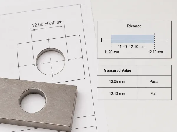
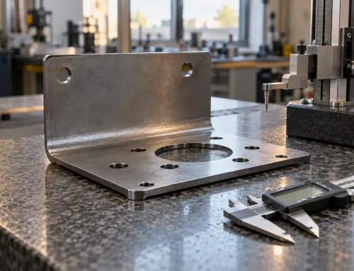
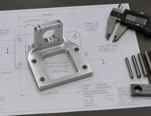
Dimensional inspection requires measured values to stay within the specified tolerance band.
The most common misconception about dimensional inspection is that it is a qualitative judgment. It is not. A drawing that specifies a bore diameter of 12.00 ±0.10 mm means exactly that: the measured value must fall between 11.90 mm and 12.10 mm. A reading of 12.13 mm is out of spec, even if the part “looks fine.”
The reason this matters is straightforward. Tolerances are not arbitrary numbers on a drawing. They are engineering constraints that ensure parts fit together, seals hold pressure, and mechanisms move freely. When an inspector decides that a dimension is “close enough,” they are effectively overriding the engineer’s design intent — often without understanding why that particular tolerance was specified in the first place.
This is why dimensional inspection must produce quantitative, traceable results. A measured value paired with a tolerance band provides clear manufacturing acceptance criteria for a pass or fail determination. “Looks good” does not.
Choosing the Right Tool: The 10:1 Rule and When to Use What
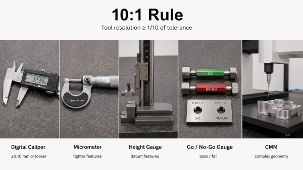
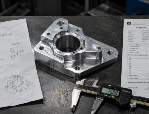
Measuring tools should provide resolution fine enough for the tolerance being inspected.
One of the most practical questions in dimensional inspection is which measuring instrument to use. The 10:1 rule provides a starting point: your instrument’s resolution should be at least one-tenth of the tolerance you are checking. For a ±0.10 mm tolerance, that means a resolution of 0.01 mm or better. Some industries and standards use different ratios — 4:1 is sometimes cited as a minimum, while 20:1 is preferred for critical measurements — but the principle is the same: if your tool is not significantly more precise than the tolerance, the measurement uncertainty itself can mask an out-of-spec condition.
Hand tools: calipers, micrometers, and height gauges
Digital calipers (resolution 0.01 mm) are the most versatile hand instrument for general dimensions — overall length, width, hole diameter, step height. They are well suited to tolerances of ±0.10 mm or looser. Outside micrometers (resolution 0.001 mm) offer better precision for tighter features such as bore or shaft diameters. Height gauges, used on a surface plate, measure step heights and datum-referenced features with similar precision.
Gauges: go/no-go pins, thread gauges, and profile gauges
Go/no-go pins and thread gauges provide a fast pass/fail check for holes and threads without returning a numerical value. They are efficient for production environments where the question is simply “in spec or not.” Profile gauges check whether a surface or contour falls within a tolerance band. The limitation of attribute gauges is that they do not tell you how close to the limit a feature is — only whether it passed.
CMMs and when hand tools are not enough
When tolerances are tighter than ±0.01 mm, or when the part has complex geometry with many interrelated dimensions, coordinate measuring machines (CMMs) become the appropriate tool. A CMM uses a touch probe to capture 3D coordinates and can achieve measurement accuracies down to ±0.005 mm or better. CMMs are especially valuable for parts with profile tolerances, position callouts, or features that are difficult to access with hand tools.
A practical quality control and inspection framework uses calipers for tolerances at ±0.10 mm or looser, micrometers and gauges for tolerances between ±0.05 and ±0.01 mm, and a CMM for anything tighter or geometrically complex. When in doubt, verify that your tool’s resolution is at least 10 times finer than the tolerance band.
Not Every Dimension Is Critical — How to Tell Them Apart
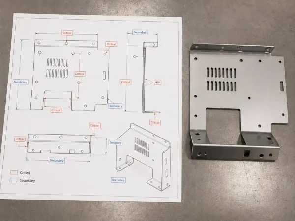
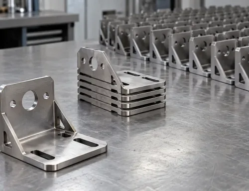
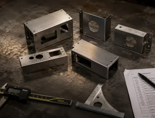
Critical dimensions control fit and function, while secondary dimensions can usually be sampled less frequently.
A typical drawing may contain dozens of dimensions. Treating all of them with equal priority wastes inspection time and obscures the dimensions that actually control fit and function. The practical distinction is between critical dimensions and secondary dimensions.
Critical dimensions are those that directly affect assembly, sealing, structural integrity, or mechanical function. On a sheet metal part, these typically include:
- Mounting hole positions relative to a datum
- Bend angles and flange lengths on formed features
- Mating surface lengths and widths
- Feature-to-feature distances that determine fit with adjacent parts
These dimensions should be prioritized during inspection — checked on every part or with tight sampling plans. Secondary dimensions include outer edge profiles, cosmetic cutouts, non-functional radii, and features with loose general tolerances. They can be sampled less frequently without compromising the integrity of the inspection.
The reason this distinction matters is practical. Inspection resources are finite. When a supplier’s inspection plan checks every dimension to the same standard, it either takes too long or spreads attention too thin. A better sheet metal inspection plan focuses inspection effort on the dimensions where failure would actually affect the part’s function — and communicates which dimensions are critical in the drawing or purchase order.
Inspection Records: What to Include and Why They Matter
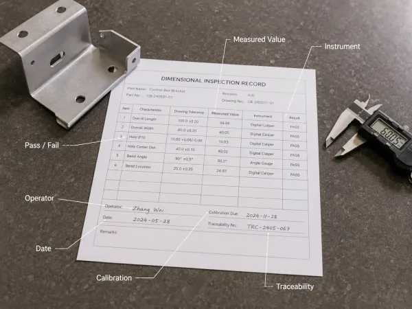
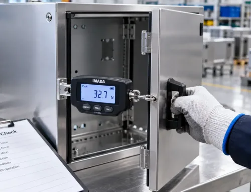
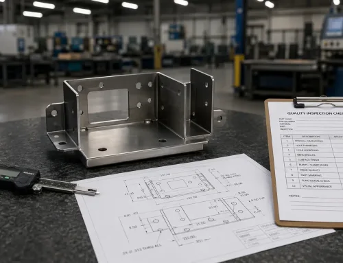
A complete inspection record should include measured values, instrument details, calibration status, traceability, and pass or fail results.
The inspection record is the only objective evidence that a part met specification at the time of delivery. When a dimensional dispute arises — a part does not fit, a customer rejects a shipment, an auditor asks for proof — the record is what settles it. Without it, measurements cannot be traced back to a specific batch or operator, and pass or fail determinations become one person’s word against another’s.
A complete inspection record should include:
- Measured value with units (e.g., 12.05 mm, not just “pass”)
- Instrument used — type and identifier (e.g., Mitutoyo digital caliper, ID# C-042)
- Calibration status — confirmation that the instrument was within its calibration period
- Operator name
- Date of inspection
- Traceability — lot number, serial number, or work order reference
- Pass or fail determination against the specified tolerance
For procurement teams, the most effective way to ensure complete records is to define the manufacturing quality requirements upfront. Include inspection expectations in your RFQ and drawings: identify which dimensions are critical, state the acceptance criteria, specify the report format you expect, and ask for instrument and calibration references. Clear requirements at the RFQ stage prevent the most common inspection-related disputes: disagreements over which dimensions were supposed to be checked, uncertainty about whether the right tool was used, and missing evidence when parts are rejected.
What Makes Sheet Metal Parts Different
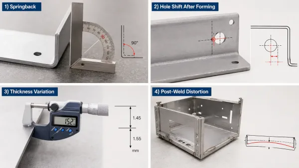
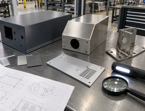
Sheet metal inspection must consider springback, hole shift after forming, thickness variation, and post-weld distortion.
Sheet metal fabrication introduces dimensional challenges that do not exist with machined parts. Understanding these challenges is the difference between an inspection plan that works and one that generates false rejects or passes bad parts.
Bend angle springback. When sheet metal is bent, the material springs back slightly after the press brake releases. A 90° bend specified on the drawing may come off the press at 88° or 91°, depending on material type and thickness, bend radius, tooling setup, and whether the press brake is CNC-controlled or manual. The achievable tolerance depends on these factors — not just what the drawing says.
Hole location accuracy after forming. Holes punched or drilled before bending shift position during the forming operation. When a part has multiple holes in different bend zones, the accumulated positional error can be significant. This is why hole-to-hole and hole-to-edge dimensions on formed parts require special attention during inspection.
Material thickness variation. Sheet stock comes with its own thickness tolerance — a nominal 1.5 mm sheet might measure anywhere from 1.42 to 1.58 mm depending on the standard and supplier. This variation affects bend radius, the resulting angle, and the overall height of formed features. It should be accounted for in the inspection plan.
Post-weld distortion. Welded assemblies can distort from residual stress, shifting dimensions away from their pre-weld values. The inspection plan should account for post-weld variation, not just the nominal geometry.
Sheet metal dimensional inspection requires judgment — understanding which tolerances are achievable with the forming process, not just checking numbers against a drawing.
Key Takeaways
- Dimensional inspection is quantitative measurement with traceable results. “Looks good” is not an inspection.
- The 10:1 rule guides instrument selection: your tool’s resolution should be at least one-tenth of the tolerance you are checking.
- Not every dimension is equally important. Focus inspection effort on critical dimensions — those that drive assembly and function.
- Inspection records are the evidence that resolves disputes. Specify what you need in your RFQ and drawings, not after delivery.
- Sheet metal parts have their own inspection challenges — springback, hole shift after forming, material thickness variation, and post-weld distortion — that require manufacturing judgment, not just numerical comparison.
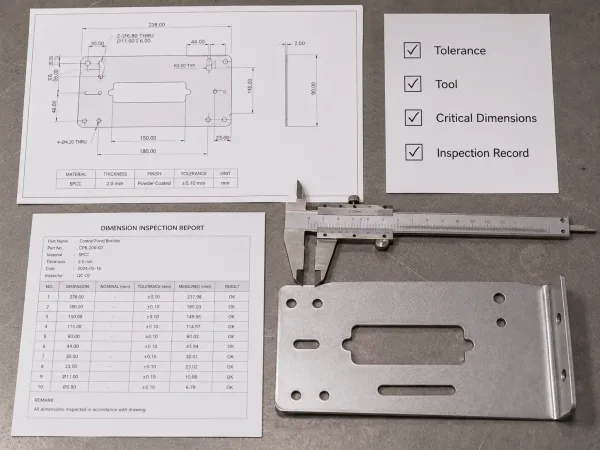
A practical dimensional inspection review should confirm tolerance, tool selection, critical dimensions, and traceable records.