
You have finished the mechanical design of a custom sheet metal chassis. The layout works, the mounting pattern is fixed, and the drawing calls for self-clinching studs at eight locations. Then a question arrives from procurement or from the fabricator: who confirms the hole sizes, the edge distances, and the installation sequence — your engineering team, or their design service?
PEM fasteners — threaded studs, nuts, and standoffs that are pressed into sheet metal, named after a PennEngineering product line that the industry now uses as a generic term — lock in as the fastener seats and displaces the surrounding material. They are the standard way to add reliable threads to sheet that is too thin to tap. How the design work around them is split between your team and your supplier determines whether parts assemble cleanly or come back as rework.
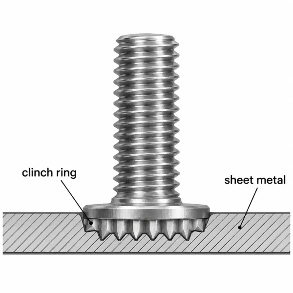
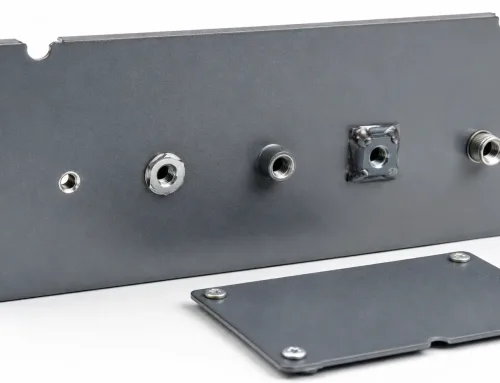
Cross-section view showing how the clinch feature of a self-clinching stud locks into sheet metal.
What a PEM Fastener Design Service Actually Covers
What gets reviewed
A useful design service starts before the quote, not after a rejected first article. The review compares the specified fastener against the sheet it will be installed in: material type and thickness, hole diameter and position, distance to edges and bends, and clearance to nearby features. It also checks whether the planned installation sequence fits with surface finishing and assembly steps.
These checks matter because self-clinching fasteners have hard limits. A stud sized for 1.0 mm sheet will not hold in 0.8 mm material, and a hole placed too close to a fold can distort during forming. Catching this at the RFQ (request for quotation) stage costs a drawing revision; catching it at first article costs scrap and schedule.
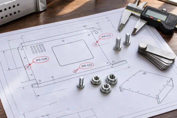
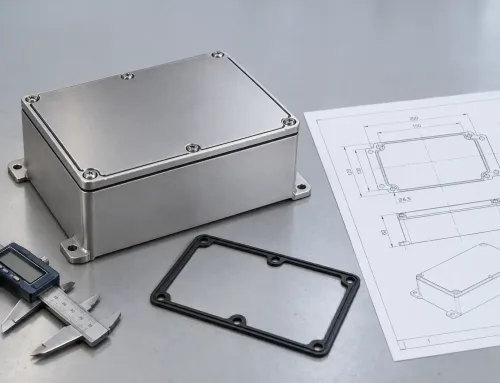
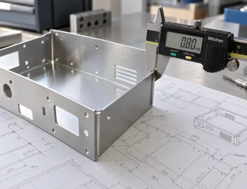
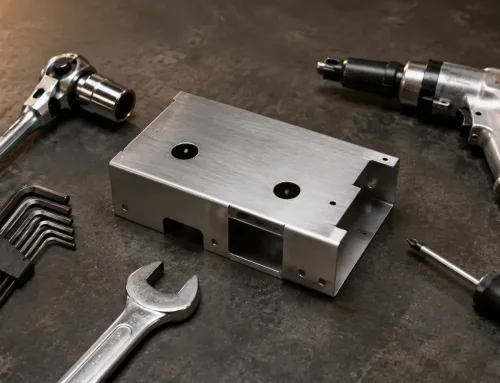
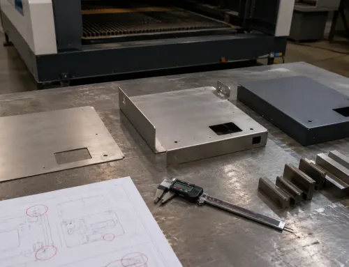
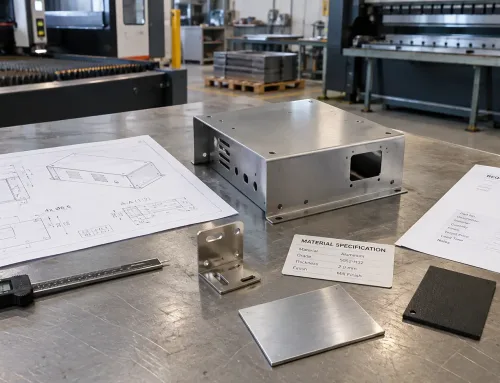
A sheet metal drawing with fastener callouts reviewed alongside self-clinching fastener samples and measuring tools.
What you get back
The deliverable is a set of concrete findings, not a brochure. Expect itemized markups on the drawing: hole diameter corrections, fastener series alternatives where the specified part is marginal, installation-sequence notes, and acceptance criteria for the install step. If a specified part number is a poor fit for the sheet material or thickness, the service should propose the next suitable series and explain the trade-off — pull-out strength, head height, or thread engagement — rather than substituting silently.
Core Design Rules: Sheet Thickness, Material, and Hole Layout
Whether you keep the work in-house or delegate it, your team needs enough of the underlying rules to review supplier input intelligently.
Minimum sheet thickness by fastener size
Self-clinching fasteners lock by displacing sheet material, so sheet thickness sets the limit on fastener size. Typical planning minimums look like this:
| Fastener size | Typical minimum sheet thickness |
|---|---|
| M2.5 / #4-40 | ~0.8 mm (0.030 in) |
| M3 to M4 / #6 to #10 | ~1.0 mm (0.040 in) |
| M5 / 1/4″-20 | ~1.2 mm (0.047 in) |
| M6 and larger / 5/16″ and up | ~1.5 mm (0.060 in) |
These are planning numbers for common carbon and stainless steel grades; the fastener manufacturer’s datasheet governs. If the panel is thinner than the table allows, the fix is a different fastener series — a flush-head or thin-sheet variant — or a different joining method, not a larger stud forced into thin stock.
Material and installation force
Sheet material changes how the fastener clinches. Low-carbon steel accepts standard installation force. Stainless steel is harder and typically needs a fastener with a hardened clinching feature or higher press force. Aluminum is softer: it clinches at lower force but is more prone to thread wear and pull-out under repeated assembly cycles. A fastener proven on a steel prototype may therefore need a different part number or press recipe once production moves to stainless or aluminum.
Hole size, edge distance, and bend clearance
The mounting hole is part of the fastener system. Hole diameter tolerances for self-clinching hardware are tighter than standard clearance holes — often H12 or better per the manufacturer’s recommendation — because the clinch feature must engage the sheet uniformly. Keep fasteners at least two times the sheet thickness from a sheared edge, and plan on two to three times the sheet thickness from the inside bend line so the clinched zone stays clear of the bend’s deformed region. Dense stud layouts need this check hole by hole, not just once per panel.
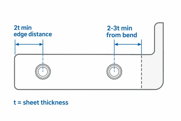
Diagram of edge distance and bend clearance rules for fastener placement on sheet metal.
In-House or Delegated: How to Split the Design Work
Keep these decisions in-house
Functional requirements belong with the people who own the product. Thread size and engagement length follow from mating parts and load cases. Service access, grounding paths, and cosmetic surfaces are product decisions. Acceptance criteria — what “installed correctly” means in your assembly — should be written by whoever is responsible for the end item.
Delegate these to the fabricator
Manufacturability details move naturally to the supplier who runs the press: fastener series selection against available sheet stock, hole position adjustments within your functional tolerance, installation force and tooling, and scheduling installation relative to cutting, forming, and finishing. A shop that installs these fasteners daily knows which series seat reliably in which material — knowledge that rarely survives in a design office that specifies them twice a year.
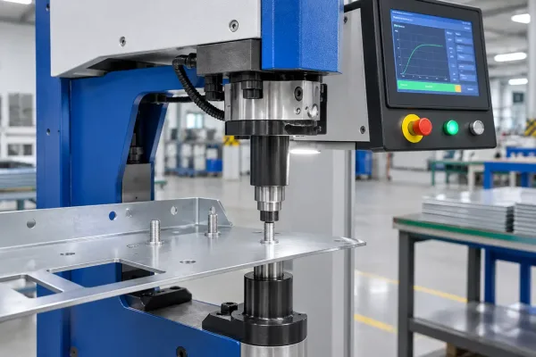
A calibrated industrial press installing self-clinching fasteners into a sheet metal panel.
What shifts the line
The boundary moves with risk. First-time PEM users, panels with high fastener counts, tight tolerance stacks, and mixed fastener families all argue for broader delegation with earlier supplier involvement. Simple bracket work with a fastener you have run in volume for years can stay almost entirely in-house. The deciding question is who carries the cost of a wrong call: if a mis-sized hole means a scrapped panel, the party that owns the press should see the drawing before it is released.
What Your Drawings and RFQs Must Specify
Calling out the fastener
Name the fastener by manufacturer part number on the drawing or in an attached fastener schedule. If alternates are acceptable, define the equivalence criteria — thread, head style, strength class, and material — instead of leaving substitution to the shop’s judgment. Ambiguity at this line item is the most common cause of clarification rounds.
Installation sequence and surface finish
Decide whether fasteners go in before or after finishing. Installing before powder coating or plating protects threads from coating buildup but risks finish damage around the head during press work; installing after finishing keeps the cosmetic face clean but exposes threads to handling damage and adds masking effort. Write the choice on the drawing — it changes both the quote and the inspection plan.
Acceptance requirements
State what gets verified after installation: fastener height or flushness, position, and — where it matters — pull-out or torque-out performance on a sampling basis. Pull-out force is the axial load needed to dislodge the installed fastener; torque-out is its rotational resistance. Both depend on sheet material and thickness, so tie acceptance values to the datasheet for the specified combination rather than to a generic number.
Installation Control: First Article to Volume Production
First article
On the first parts, verify the full set of installation variables: hole diameter, position, installation height, and surface condition around the fastener. This is where a mismatch between drawing callout and press setup shows up — while it is still confined to a few parts.
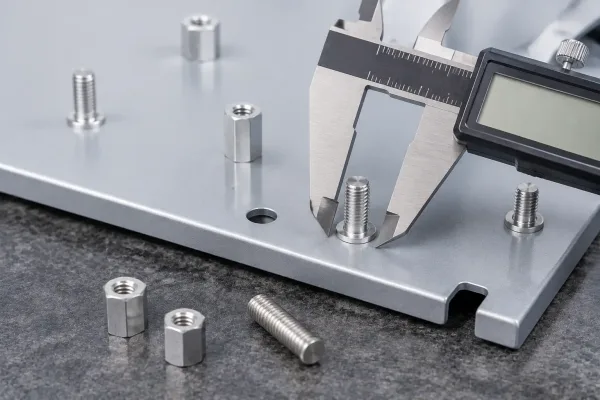
A digital caliper checking the installation height of a self-clinching stud on a first-article panel.
Volume production
In volume, the focus moves from inspecting every dimension to monitoring the process. Calibrated presses with force monitoring track installation force cycle by cycle, and pull-out or torque-out checks move to a sampling plan agreed with the buyer. Consistent seating depth across the run matters more than single-part perfection: a proud fastener on the last unit blocks assembly just as surely as one on the first.
What to agree at RFQ
Settle the inspection plan during quotation: which characteristics are checked on every part, which are sampled, and which records — installation force logs, certificates of conformance, first-article reports — ship with the parts. Agreed at the RFQ stage, this is paperwork. Discovered at goods-in, it is a dispute.
When a Design Review Pays Off — and What Goes Wrong Without One
A pre-quote design review earns its cost when the project is new to PEM hardware, when the panel is thin or densely populated with fasteners, when tolerances stack across an assembly, or when the supplier is remote and iteration cycles are long. In those conditions, an hour of review replaces days of re-quoting.
The failure modes are predictable. Fasteners placed too close to a bend deform or crack during forming. Plating or powder coat thickness eats the thread engagement calculated from nominal sheet thickness. Fasteners installed after finishing end up with damaged or coated threads when masking is sloppy. And a series chosen for steel fails when production moves to stainless or aluminum. None of these are exotic; they are the routine cost of leaving fastener design implicit.
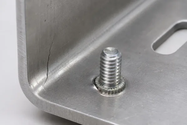
A formed sheet metal part with a crack near the bend where a fastener was placed too close.
FAQs
On your next project with self-clinching hardware, put the fastener callouts and acceptance criteria on the drawing, mark which decisions you own and which you want reviewed, and request the design review before the quote is finalized. That is the point where the design work is still cheap to change — and where the split between your team and your fabricator does the most good.