
Rolling direction is easy to file under paperwork. It appears on mill certificates and packing slips, and most people read it as a shipping detail — or as a synonym for the brushed texture on an exposed surface. On a formed sheet metal part, that classification is expensive. Rolling direction is a mechanical property of the sheet: it changes strength, elongation, bend cracking risk, and how parts should be oriented on the plate before cutting. This entry defines the term, shows what it does to formed parts, and explains how to specify it.
What Goes Wrong When Rolling Direction Is Ignored
A Flange That Cracks in Only One Orientation
A 1.5 mm stainless flange cracks along the bend radius on the first batch, on the same tooling, program, and press brake as before. Rotate the blank 90° and the next batch bends clean. Nothing in the material changed — the bend line ran parallel to the rolling direction instead of across it. Fabricators see this often enough to ask about orientation before quoting tight-radius bends.
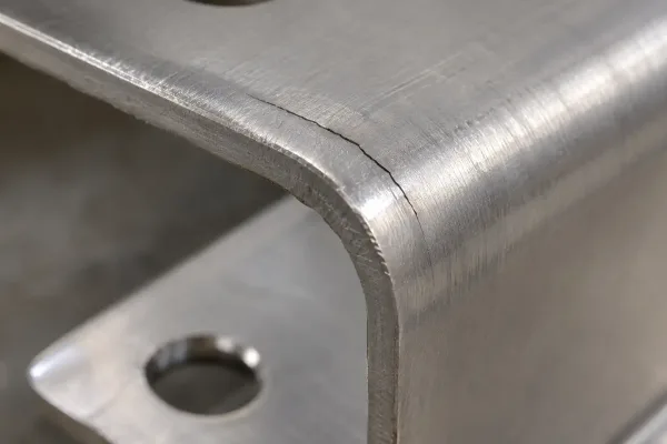
Cracking at the bend radius of a stainless flange bent parallel to the rolling direction.
What Inconsistent Orientation Does to a Batch
Direction problems rarely stop at a single part. When blanks from the same sheet are nested with bend lines in mixed orientations, the batch splits: some parts crack at the radius, others form fine, and springback (the angle a part keeps after it leaves the tooling) drifts between the two groups. Inspection sees a dimensional problem; the root cause is layout. Keeping orientation consistent is cheaper than sorting parts after forming.
What Rolling Direction Is and How Rolling Creates It
From the Rollers to the Sheet: How Directionality Develops
Rolling direction is the direction in which the sheet passed through the working rolls during rolling. Thickness reduction forces the metal to elongate along the rolling path. Grains and hard inclusions stretch into long stringers — streaks of elongated structure aligned with that path — while the structure through the thickness stays compressed. The result is anisotropy, meaning material properties that change depending on the direction you measure them. Annealing softens the texture but rarely removes the difference completely.
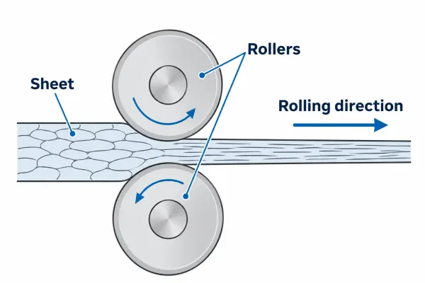
Sheet passing through the mill rolls: grains and inclusions elongate along the rolling direction.
Rolling Direction vs. Grain Direction: What Each Term Covers
The two terms describe one axis from two sides. Rolling direction names the manufacturing input: the path the strip took through the mill. Grain direction names the material’s response: the orientation of the elongated structure that rolling produced. On sheet metal drawings they almost always mean the same axis, and shops treat them interchangeably. In precise usage — on test reports, for example — rolling direction is the geometric reference; grain direction is what you observe in the material. (See also: Grain Direction.)
Along vs. Across: How Mechanical Properties Change
L vs. T: Strength, Elongation, and Formability
Test reports label specimen orientation with standard letters: L for longitudinal (parallel to the rolling direction), T for transverse (across it), and C for through-thickness. The differences between L and T are modest on mild steel and significant on some stainless and aluminum grades, but the trend is consistent: strength runs slightly higher along the rolling direction, while ductility is better across it. Through-thickness ductility is the lowest of the three, because the stringers rolling creates are oriented to separate in that direction.
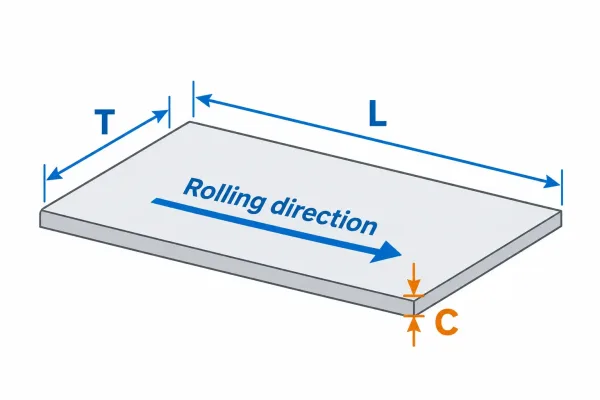
L runs parallel to the rolling direction, T across it, and C through the thickness.
Deep-drawing grades add one more measure — the r-value, or plastic strain ratio, which rates how well the sheet resists thinning. It is reported at 0°, 45°, and 90° to the rolling direction, so drawing performance is directional even within one coil.
The table below summarizes how typical sheet behaves. Exact values depend on alloy, temper, and reduction ratio; treat the trend as the design input, not a guaranteed number.
| Property | Along rolling direction (L) | Across rolling direction (T) |
|---|---|---|
| Yield and tensile strength | Slightly higher | Slightly lower |
| Tensile elongation | Slightly lower | Slightly higher |
| Bendability at a given radius | Lower — cracks open sooner | Higher — tighter radii achievable |
| Deep-drawing behavior | Depends on directional r-values | Governed by average r-bar |
Reading Directional Data Before You Design the Part
If your part bends, draw formability conclusions from the direction that matches the bend line, not from the best number on the page. Where the certificate does not state specimen orientation, ask before the material is cut.
Bending Across vs. Along: Rules That Prevent Cracks
Why Bends Along the Rolling Direction Open Cracks
Bending stretches the outer surface of the flange. When the bend line runs parallel to the rolling direction, that stretch pulls along the stringers rolling created — the paths of least ductility in the sheet. Micro-voids open at inclusion sites and link up into a crack at the radius. When the bend line runs across the rolling direction, the same stretch crosses the stringers instead of following them, and the metal can thin before it tears.
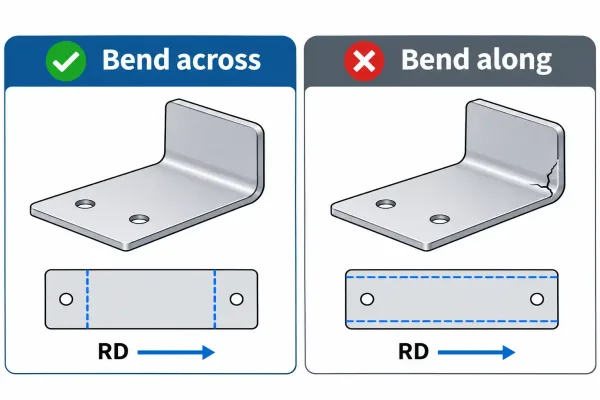
Left: bend line across the rolling direction forms clean. Right: bend line along it cracks at the radius.
The High-Risk Combinations
Bending parallel to the rolling direction is not automatically fatal; risk is a combination of factors. The pairings below raise cracking probability fast enough to matter at quote time:
- Bend line parallel to the rolling direction with an inside radius under 1× material thickness (under 2× for stainless and heat-treated aluminum)
- Thick stock relative to radius — outer-fiber strain rises as the radius-to-thickness ratio falls
- Low-ductility conditions: T6 aluminum, harder stainless tempers, heavily reduced material with no formability grade
- Sheared or punched edges placed in the tension zone of the bend
The comparison below captures the difference at a glance (t = material thickness):
| Condition | Bend line across rolling direction | Bend line along rolling direction |
|---|---|---|
| Typical minimum inside radius, mild steel | ~0.5t | ~1t |
| Typical minimum inside radius, stainless 304 | ~1t | ~2t |
| Crack risk at equal radius | Lower | Higher |
| Preferred choice when layout allows | Yes | Avoid for tight bends |
When a design cannot rotate, increase the inside radius and tell the fabricator which way the material runs.
Nesting: Choosing Part Orientation on the Sheet
The Trade-off Between Material Yield and Preferred Orientation
Nesting — the layout of parts on a sheet before cutting — is optimized to minimize scrap. That objective sometimes points bend lines along the rolling direction, especially on long brackets that fit the sheet one way only. For flat parts with no forming, yield wins. For parts with critical bends, orientation wins: a few percent of extra scrap costs less than a cracked flange or a re-cut batch. Mark orientation constraints on the flat pattern so the nesting engineer sees them before nesting starts, not after.
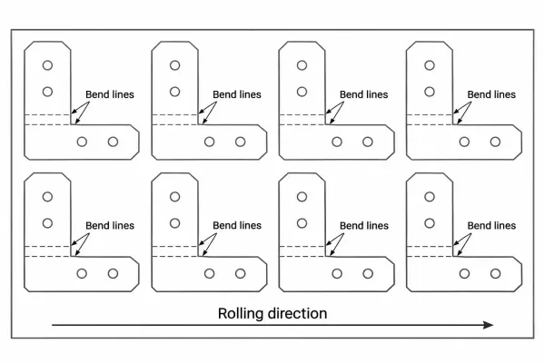
Parts nested with bend lines kept across the rolling direction on every blank.
Keeping Orientation Consistent from Sample to Production
Sample runs and production runs often come from different sheets or coils, nested separately. If orientation is not specified, each run resolves it on its own, and the second run can behave differently even though the drawing has not changed. One note on the drawing or RFQ (request for quote) carries the decision through purchasing, nesting, and forming — and keeps first-article checks comparable between samples and production.
Specifying Rolling Direction: Drawings, Certificates, and Shop Defaults
Drawing Callouts That Work at Quote Time
A workable callout is short and testable: “Bend lines shall run across the rolling direction,” or “Rolling direction as shown on flat pattern,” with an arrow on the flat-pattern view. Put it where the fabricator looks first — the flat-pattern sheet or the general notes — not buried in a title block. If direction affects assembly or appearance, name the affected faces so inspection knows what to check.
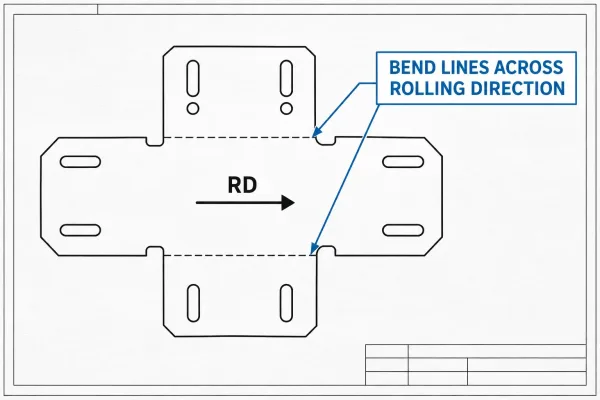
A flat-pattern callout that tells the fabricator which way the rolling direction must run.
What L, T, and C Test Pieces on the Mill Certificate Tell You
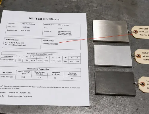
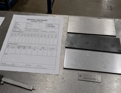
Certified mechanical properties belong to the orientation of the specimen that produced them. L specimens are cut parallel to the rolling direction, T specimens across it, and C specimens through the thickness. A report listing only L-direction data says nothing about transverse elongation — the number that usually governs bend performance. When forming matters, read the certificate the way you read a drawing: in the direction the part will be stressed.
The Shop Default When the Drawing Is Silent
Fabricators cannot invent a direction. When the drawing does not name one, the shop nests for material yield and follows the incoming sheet’s rolling direction — usually the long dimension of standard plates and coils. That default is reasonable — and invisible until a bend cracks. A single line in the RFQ prevents the dispute: state whether orientation matters and where. If you are unsure how your part’s bends interact with rolling direction, ask a fabricator to review the flat pattern at quote stage, before nesting decisions harden into production.
FAQs
Rolling direction is fixed at the mill, but its consequences are decided on your drawing.