
Specifying a shielding finger for a sheet metal enclosure looks like a part-selection problem. Pick a beryllium copper strip, clip it into the seam, and the enclosure is shielded. In practice, that assumption fails at the same point every time: the contact between the finger and the sheet metal. A finger stock that performs on the datasheet can deliver poor shielding once it is installed on real parts—because the slot tolerance drifted, the surface finish insulated the contact face, or the compression range never matched the assembly gap. Shielding performance is determined less by which finger you buy than by how the sheet metal around it is designed, finished, and documented.
Why Enclosure Seams Defeat RF Shielding — and Where Fingers Fit In
Every joint in a metal enclosure—lids, panels, doors, removable covers—is a potential leak path for electromagnetic interference (EMI). Even a seam that looks tight to the eye can let RF energy through if the two metal surfaces are not electrically continuous at high frequency. Slots and gaps act as slot antennas: at certain frequencies, a gap as small as a few millimeters can radiate or admit significant energy.
A shielding finger—also called finger stock or an EMI gasket finger—closes that gap. It is a spring-metal contact strip that spans the seam between two conductive surfaces, maintaining electrical continuity even when the parts move, vibrate, or are repeatedly opened and closed.
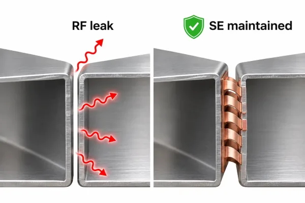
Diagram showing RF energy leaking through an open sheet metal seam on the left, and a shielding finger maintaining electrical continuity across the seam on the right.
What a shielding finger actually does
The mechanism is straightforward: the finger creates a low-impedance electrical bridge across the joint. When both sides of the seam are bonded through the finger to a common ground, the seam stops acting as an antenna. Shielding effectiveness (SE)—the measure of how much RF energy a barrier blocks, expressed in decibels (dB)—depends on this continuity. A single unshielded seam can reduce enclosure SE by 20 dB or more, which is the difference between passing and failing an emissions test.
This is why fingers are specified in the first place: they are not decorative hardware. They are electrical components whose performance depends entirely on the mechanical design around them.
What Makes Shielding Finger Design Harder Than It Looks
Once you understand that the finger must maintain reliable electrical contact across a seam that moves, the design stops being a clip-and-go exercise. Three variables that are easy to overlook on a drawing each have the power to cancel the finger’s benefit.
Contact pressure and compression range
Every finger stock has a defined operating range: a free height, a working compression, and a maximum compression beyond which the spring takes a permanent set. If the assembly gap is too large, the finger barely touches—contact resistance rises and shielding drops. If the gap is too small, the finger is crushed past its elastic range and loses its spring force after a few cycles. The compression window is often narrow (a common working range is 20–40% deflection of the free height), and it must be matched to the stack-up of the sheet metal parts it bridges.
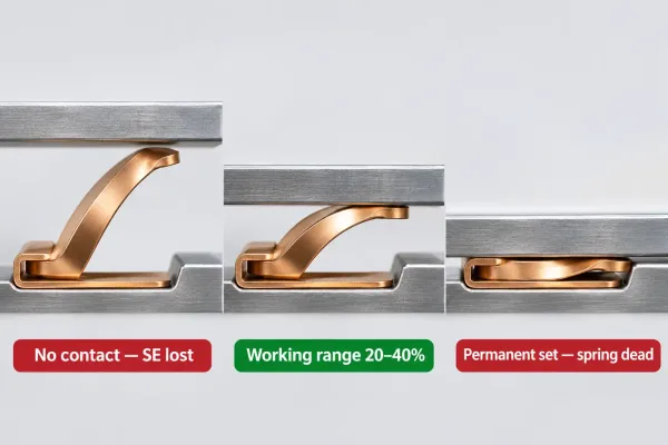
Diagram showing the three compression states of a shielding finger: free height (no contact), working range (20–40% deflection), and over-compression (permanent set).
Mounting tolerances stack up
The finger does not float in space. It sits in or on a sheet metal feature—a slot, a flange, a folded edge—and that feature has tolerances. Slot width, flange height, and flatness all affect how evenly the finger is compressed along its length. A slot that is 0.1 mm too wide at one end and 0.1 mm too tight at the other produces uneven contact: the loose section leaks, the tight section deforms. On long seams (enclosure lids, rack-mount front panels), these variations accumulate.
Surface finish conflicts
The finger must touch bare or conductive metal. If the contact zone is powder-coated, anodized, or painted, the coating acts as an insulator—even a thin one. The finger is now pressing against a dielectric layer, not metal, and the electrical bridge is broken. This is not a rare mistake. It happens whenever the surface finish callout covers the entire part and the drawing does not flag the contact area as a masking zone.
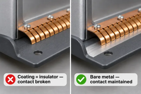
Left: contact zone covered with powder coating — the finger touches an insulating layer and shielding fails. Right: contact zone masked and left as bare conductive metal — the finger bonds electrically to the enclosure.
Finger Types and How They Interface with Sheet Metal
After the hidden variables are clear, the next question is which finger type fits the design. The choice determines what the sheet metal must provide.
| Finger type | Typical material | Attachment | Sheet metal interface |
|---|---|---|---|
| Clip-on finger stock | Beryllium copper (BeCu), often plated | Press-fit into a slot or over an edge | Precision slot width; edge geometry |
| Adhesive-backed strip | BeCu or stainless steel with conductive adhesive | Bonded to a flat flange | Flat, clean surface; no coating under adhesive |
| Formed sheet metal fingers | Same material as the enclosure (e.g., stainless, mild steel) | Integral to the part—cut and formed in one operation | Bend geometry; no separate component |
| Spring-loaded contact clips | Stainless steel or BeCu | Screwed or riveted | Mounting holes; boss or flange design |
Beryllium copper finger stock
BeCu is the most common finger material because it combines high electrical conductivity with excellent spring recovery. It tolerates repeated compression cycles without losing force. Most BeCu finger stock is supplied as a formed strip that clips into a precision slot or over a folded edge. The sheet metal must hold the strip securely and position it so that the spring fingers align with the mating surface. If the slot is too loose, the strip rattles or shifts; if too tight, installation deforms the fingers.
Formed sheet metal fingers
An alternative is to form the fingers directly from the enclosure material—cutting a comb pattern into the sheet and bending each tooth outward to act as a spring contact. This eliminates a separate component and can reduce assembly time. The trade-offs are design constraints: the finger properties are limited by the sheet material and thickness (a 0.5 mm stainless tooth has less spring travel than a 0.1 mm BeCu strip), and the forming operation adds complexity to the cutting and bending process. Formed fingers work well when the enclosure is already sheet metal and the sealing requirements are moderate.
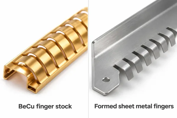
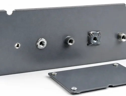
Left: a beryllium copper clip-on finger stock strip. Right: shielding fingers formed directly from a sheet metal panel. Both shown on a neutral background.
Designing the Sheet Metal Mounting Structure
Regardless of the finger type, the sheet metal must carry a purpose-built mounting feature. This is where shielding design meets fabrication reality—and where the drawing must communicate clear intent.
Slot and flange geometry
For clip-on finger stock, the slot is the critical feature. Slot width must match the finger’s mounting tab or base thickness, typically within ±0.05 mm for a reliable press fit. Slot depth controls how far the finger protrudes and therefore how much compression it sees at the assembly gap. On flanges, the height and flatness of the flange determine whether the finger contacts the mating surface evenly. A flange that bows by 0.2 mm over a 200 mm span will produce visible contact variation—often enough to degrade SE at higher frequencies.
Useful starting geometry for clip-on stock includes a slot width of the finger base thickness plus 0.05 mm, a flange at least 5 mm wide to support the finger, and a protrusion height that puts the finger at mid-compression when the assembly is closed. These are starting points, not final values—the finger supplier’s datasheet should drive the exact numbers.
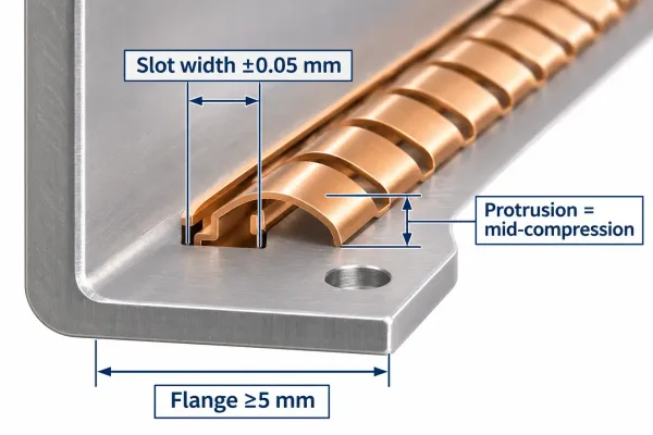
Dimensioned diagram of a sheet metal flange with a mounting slot for clip-on finger stock: slot width, flange width, and finger protrusion height are labeled.
Bend interaction and edge distance
Mounting features near a bend line need extra attention. When the sheet is bent, material stretches on the outside of the bend and compresses on the inside; a slot placed too close to the bend can distort, changing its width or its angle. As a working rule, keep mounting slots at least 3× the material thickness away from the bend line, or confirm with the fabricator that the feature can be cut after forming. Edge distance matters too: a finger feature within 2× the material thickness of a cut edge is more likely to deform during handling and may compromise both the mount and the contact.
Surface Finish and Electrical Contact at the Interface
The surface finish of the enclosure is one of the most common sources of shielding failure—and one of the easiest to prevent with a drawing note.
Conductive vs. insulating finishes
Conductive finishes preserve electrical contact. These include bare metal, zinc plating, nickel plating, chromate conversion coatings (e.g., Iridite on aluminum), and conductive anodizing in specific grades. Insulating finishes—standard powder coating, liquid paint, Type II non-conductive anodizing—break the contact path wherever they cover the finger interface.
The practical decision is binary at the contact zone: the finger must touch conductive material. Everywhere else, the finish can serve its intended purpose (corrosion protection, appearance, hardness). On most enclosures, this means specifying a masking zone on the drawing: the contact surface, and often the finger slot itself, stays uncoated.
Masking requirements on drawings
Masking is not something the fabricator will assume. If the drawing calls for powder coating on the entire part, the entire part will be coated—including the flange where the finger sits. A clear callout is required: note the contact area dimensions or reference a shaded zone in the drawing view, and state explicitly that no coating is permitted in that area. For anodized aluminum, the same note applies, and the mask must be in place before the anodizing tank—retroactive masking after finishing is not reliable.
Drawing Callouts: What the Fabricator Needs to See
A shielding finger that works on the bench but fails in production usually traces back to an incomplete drawing. The fabricator cannot design around information that was never specified.
Key dimensions and tolerances to specify
The following callouts should appear on the drawing or in the associated notes:
- Slot or flange dimensions — width, depth, and height, with tolerances tight enough to hold the finger’s compression range (typically ±0.05 mm on width for clip-on stock).
- Finger specification — supplier part number or a complete description (material, plating, profile, free height) if the fabricator is sourcing the component.
- Contact zone definition — the exact area where bare or conductive metal is required, referenced to datums or dimensioned from edges.
- Surface finish callout — the general finish plus the masking exception for the contact zone.
- Assembly gap or compression target — the nominal gap between mating surfaces, so the fabricator can verify the finger is in its working range.
- Grounding requirement — where the finger bonds to the enclosure ground, if it is not through the mount itself.
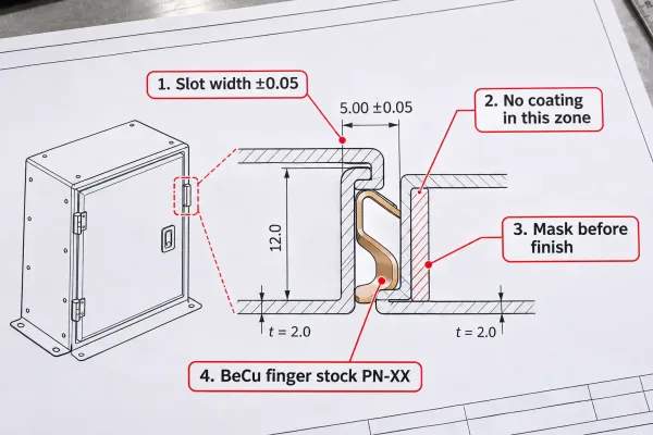
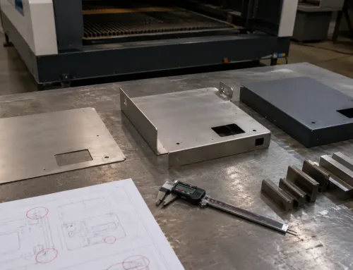
A sheet metal drawing with callout notes for a shielding finger mounting feature: slot tolerance, contact zone masking area, surface finish specification, and finger part number.
What happens when the drawing stays silent
A drawing that shows the finger but omits the contact zone or the slot tolerance forces the fabricator to fill the gap with assumptions. Typical defaults include applying the general surface finish to all surfaces, machining the slot to a generic ±0.1 mm tolerance, and treating the finger as an assembly detail rather than a functional feature. Each of these assumptions can compromise shielding—and none of them will trigger a question at the quote stage, because the part looks complete on paper.
From Prototype to Production: Keeping Shielding Performance Consistent
A prototype that passes an emissions check does not guarantee that production units will behave the same way. Shielding performance is sensitive to variations that only appear across batches.
The contact path depends on a chain of tolerances: the sheet metal’s flatness and slot dimensions, the finger’s free height and spring force (which vary slightly between material lots), and the assembly method (press-fit depth, adhesive bond quality, or forming consistency). In a single prototype, these variables are controlled by hand. Across hundreds of units, they drift. Contact resistance that was low on the first article can rise if the slot widens by 0.05 mm in production tooling wear, or if the finger supplier changes plating thickness.
For that reason, shielding-critical dimensions should be treated as key characteristics at inspection: slot width, flange height, and contact zone surface condition are worth measuring on first articles and on periodic production checks, not just on the prototype. If the enclosure will be assembled in volume, a simple contact-resistance test (a four-wire measurement across the seam at a few points) is a more reliable acceptance check than a visual inspection.
Before you release the drawing, walk through the electrical path from the finger, through the mount, to the enclosure ground—and confirm that every surface on that path is specified as conductive, every dimension that controls compression has a tolerance, and the contact zone is explicitly masked from coating. If you want a second pair of eyes on the mounting structure before it goes to fabrication, our engineering team reviews shielding-related features during the RFQ stage and flags manufacturability risks early.
FAQs