Passing a sample approval does not mean an enclosure order is ready for mass production.
It means the supplier can make one good unit.
The gap between “one good unit” and “one thousand consistent units” is where most production problems begin—and where a proper readiness review saves the most money.
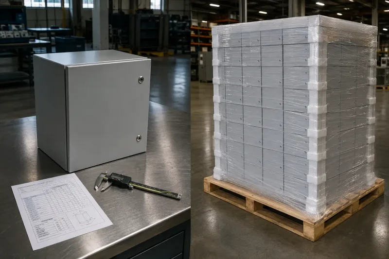
Left side shows a single polished metal enclosure on a workbench with calipers beside it; right side shows a full pallet stacked with dozens of identical enclosures wrapped in protective film. This visual contrast highlights the gap between sample approval and mass production readiness.
A production readiness review is a structured check of:
- Drawings
- Materials
- Tooling
- Quality plans
- Packaging
- Logistics
It takes place before the factory switches from prototype or pilot production to high-volume sheet metal manufacturing.
For OEM buyers ordering custom sheet metal enclosures, this review can mean the difference between a smooth production ramp-up and a container of parts that do not assemble correctly.
What Production Readiness Actually Means for Metal Enclosures
Sample approval verifies that a supplier can produce a part according to the drawing.
Production readiness verifies that the supplier can repeat that result across the entire order without relying on manual correction.
During the sample stage, an operator may:
- Hand-finish a bend
- Adjust a fixture by eye
- Select material from a known-good batch
- Manually correct a surface defect
- Rework a part until it fits
These shortcuts usually disappear during mass production.
A laser cutter processes hundreds of sheets. A press brake operator forms hundreds of bends per shift. Surface treatment lines process parts in large batches. Each step in the sheet metal production workflow introduces variation that a single approved sample may never expose.
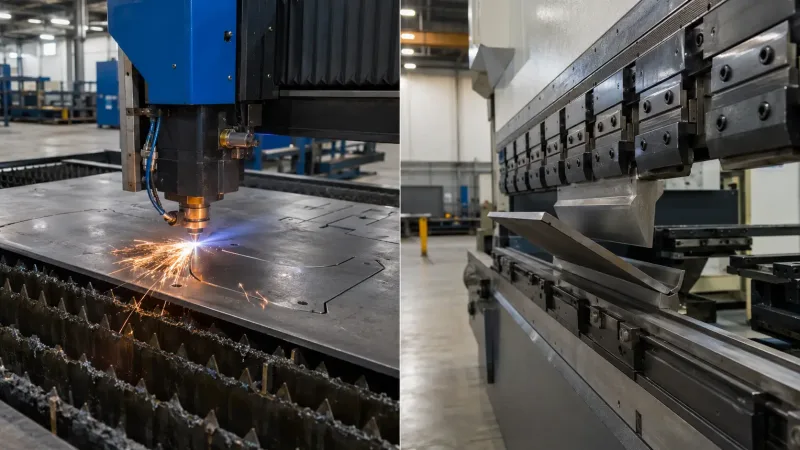
Two-panel image showing key production processes: a fiber laser cutter processing a sheet of steel with sparks visible at the cutting point, and a CNC press brake forming a precise bend on a metal panel. These are the high-throughput operations where variation is most likely to occur during mass production.
This is why production readiness must be evaluated separately.
The question is no longer:
Can this part be made?
The real question is:
Can this part be made consistently, at volume, within the agreed tolerances and delivery window?
Drawing and Documentation Baseline
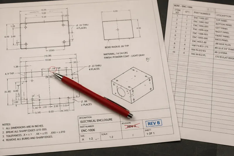
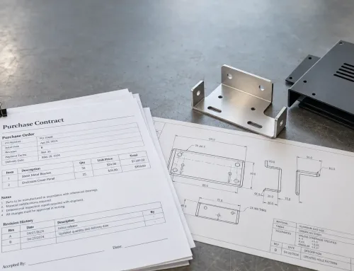
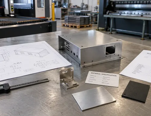
A detailed engineering drawing for a sheet metal enclosure is spread flat on a work surface. The drawing shows multiple revision stamps (REV A crossed out, REV B marked as current), dimension callouts, bend notes, and a bill of materials block. A red pen circles a critical dimension. This illustrates the importance of working from the latest approved drawing revision.
The most common source of production disputes is an incomplete, unclear, or outdated drawing.
Before mass production begins, the complete 2D drawing package must be finalized and locked.
Confirm the Latest Drawing Revision
Make sure the supplier is working from the latest approved revision.
If the drawing has gone through multiple iterations, include a revision history so everyone understands which version is active.
The drawing package should clearly identify:
- Drawing number
- Revision number
- Revision date
- Approved changes
- Superseded versions
Mark Critical Dimensions
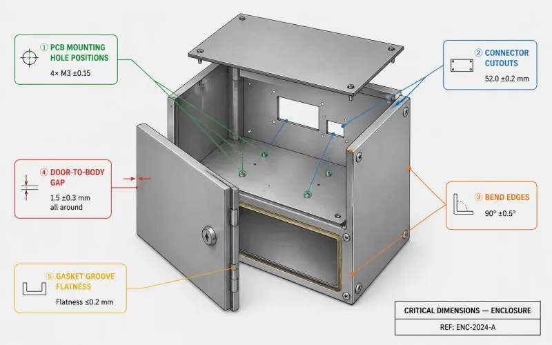
An isometric technical diagram of a rectangular sheet metal enclosure with key dimensional features highlighted using color-coded callout lines. Each callout labels a critical dimension category: PCB mounting hole positions (green), connector cutout locations (blue), bend angle tolerances (orange), door-to-body gap (red), and gasket contact surface flatness (yellow). Tolerance values are shown next to each callout in a clean, minimal format. The diagram uses a light gray background with the enclosure rendered in a neutral steel color to keep focus on the dimensional annotations.
Critical dimensions are the dimensions that affect:
- Assembly fit
- Hardware installation
- Enclosure function
- Door alignment
- Connector positioning
- Gasket compression
- PCB mounting
- Panel appearance
General tolerances such as ISO 2768 may cover standard features, but any dimension that interfaces with a PCB, connector, gasket, hinge, latch, or mounting bracket should have its own tolerance callout.
Finalize the Bill of Materials
The documentation package should include a complete bill of materials covering:
- Material grade
- Sheet thickness
- Surface finish
- Fasteners
- Hinges
- Latches
- Grounding hardware
- Purchased components
- Installed positions
If the enclosure uses PEM fasteners or other self-clinching hardware, list each item with its part number and installation location.
Ambiguity in the BOM leads to guesswork on the production floor.
Key Quality Checkpoints Before Mass Production
The project-specific sheet metal inspection plan should define:
- What will be inspected
- How it will be inspected
- How often inspections will occur
- Which standards apply
- What happens when a part fails
This should not be a generic ISO quality statement.
It should be a project-specific plan tied directly to the critical features of the enclosure.
Material Verification
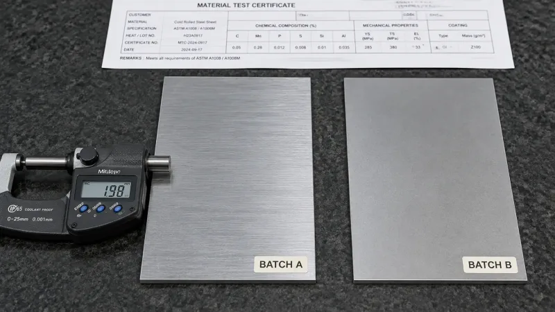
Two sheet metal samples from different mill batches are laid side by side on a surface plate. A digital micrometer displays the thickness reading of each sample. Subtle differences in surface grain direction and finish are visible. Material test certificates are partially visible in the background. This image illustrates why incoming material verification is essential before mass production begins.
Ask the supplier to confirm that the production material specifications match the approved sample in:
- Material grade
- Sheet thickness
- Surface condition
- Supplier or mill source
- Mechanical behavior where relevant
Sheet metal suppliers may switch mills or material batches between orders.
Small differences in ductility, hardness, grain direction, or surface condition can affect bend angles, cracking risk, flatness, and coating adhesion.
Dimensional Inspection
Inspection should focus on the features that control assembly and function, including:
- Hole positions
- Bend angles
- Flange lengths
- Overall dimensions
- Flatness of mating surfaces
- Door and panel alignment
- Hardware locations
- Connector cutouts
For welded enclosures, also define acceptable limits for:
- Weld appearance
- Weld bead size
- Weld position
- Heat discoloration
- Spatter
- Distortion
- Visible and non-visible surfaces
Surface Finish Consistency
Surface finish should have its own inspection checkpoint.
The powder coating specification should define:
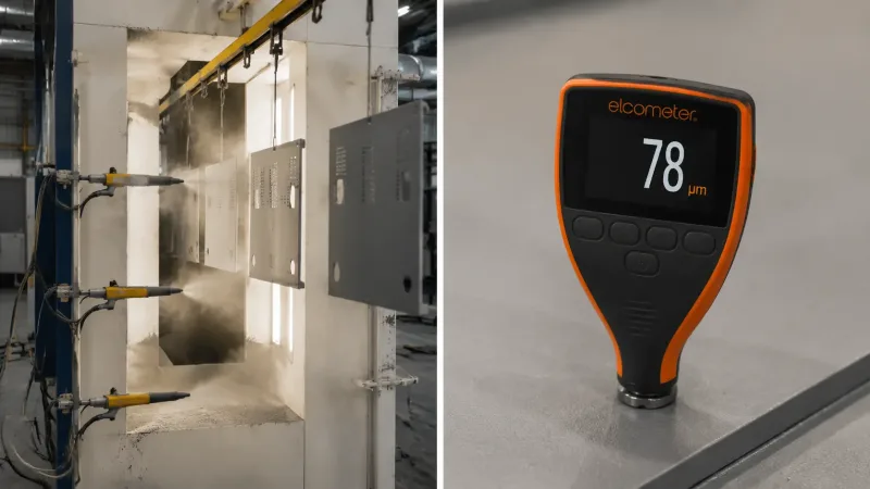
Left: an automated powder spray booth with electrostatic spray guns applying powder to metal enclosure panels hanging on a conveyor line. Right: a close-up of a digital coating thickness gauge pressed against a finished powder-coated surface, displaying a reading in microns. Consistent coating thickness and appearance across an entire production batch requires tight control of line parameters.
- Powder coating thickness
- Color reference
- RAL or Pantone code
- Texture or gloss level
- Masking boundaries
- Internal surface coverage
- Acceptable cosmetic defects
- Batch-to-batch consistency
A coating that passes on one sample may still vary across a full production batch if line parameters are not controlled.
Tooling and Fixture Validation
Tooling and fixture validation is one of the most frequently skipped checkpoints—and one of the most expensive to ignore.
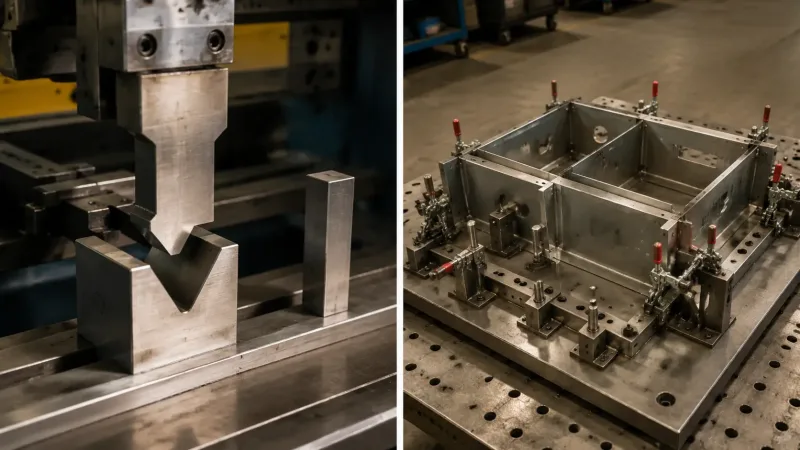
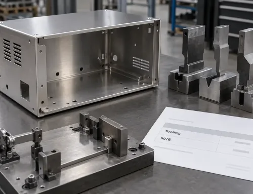
A two-part image: left shows a set of press brake punch and die tooling mounted on a machine, with different radius inserts visible; right shows a custom welding fixture jig designed to hold enclosure panels in precise alignment during spot welding. These are the dedicated tools that must be validated before production begins to ensure consistent part quality.
Samples are often produced using temporary tooling, manual adjustment, or one-off fixtures.
Mass production requires dedicated tools and fixtures that can maintain the required tolerances across hundreds or thousands of cycles.
These may include:
- Press brake tooling
- Welding fixtures
- Assembly jigs
- Inspection gauges
- Positioning fixtures
- Drilling or tapping fixtures
- Hardware installation tools
If tooling is not validated before the production run, the first batch effectively becomes the validation batch.
By that point, any tooling error may already exist in dozens or hundreds of parts.
Validate Bending Tools and Sequences
Ask the supplier to confirm that:
- Bending tools match the approved bend radii
- Bend allowances are correct
- Bend deductions are documented
- The bending sequence is defined
- Long and short flanges do not interfere with the tooling
- Springback compensation is controlled
- Operators are using the approved setup
For enclosures with multiple sheet metal bending operations, the sequence is especially important because one incorrect operation can make later bends impossible or distort the part.
Validate Welding and Assembly Fixtures
Fixtures should hold components in the correct position during welding and assembly.
This is especially important for enclosures requiring consistent:
- Door gaps
- Panel alignment
- Hinge positions
- Latch engagement
- Mounting hole locations
- Gasket compression
- Overall squareness
A mounting hole shift of only 0.3 mm may not be obvious on one sample, but it can become a visible or functional defect across a production batch.
What the Buyer Needs to Prepare
Production readiness is not only the supplier’s responsibility.
The buyer also needs to prepare clear requirements before production begins.
Define Packaging Requirements
Packaging should be finalized before the parts enter production.
Coated panels and finished enclosures may require:
- Protective film
- Foam sheets
- Corner protectors
- Part-separation dividers
- Custom cartons
- Custom pallets
- Moisture protection
- Scratch-resistant wrapping
- Special stacking methods
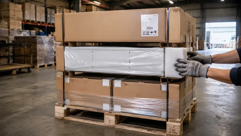
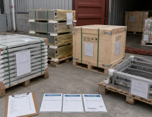
Finished powder-coated metal enclosures are shown in various stages of packaging: one unit wrapped in protective PE film with foam corner protectors fitted, one unit placed in a custom-fit corrugated carton with part-separation dividers, and a fully packed pallet with stacked cartons and edge protectors secured by strapping. Proper packaging prevents scratches, dents, and coating damage during international transit.
If the destination has specific labeling, carton size, pallet, or handling restrictions, communicate them when placing the order—not after the parts have already been packed.
Confirm the Delivery Timeline
Establish a clear production and delivery schedule with enough time for:
- Incoming material
- Production
- Pre-shipment inspection
- Rework
- Packaging
- Shipping
- Customs clearance
- Final assembly
If the enclosure is part of a larger assembly, confirm that upstream components such as PCBs, cables, power supplies, displays, connectors, and internal brackets will be available on the same schedule.
A completed enclosure that arrives before its internal components creates unnecessary storage, handling, and damage risk.
Document Acceptance Criteria
Acceptance criteria should always be written.
A verbal agreement about “good quality” is not measurable or enforceable.
Attach a clear acceptance standard to the purchase order covering:
- Critical dimensions
- Cosmetic requirements
- Surface finish standards
- Inspection sample size
- Packaging requirements
- Acceptable defect limits
- Handling of non-conforming parts
- Rework responsibilities
- Replacement or credit procedures
Common Failure Modes When Readiness Is Skipped
The same problems appear repeatedly across OEM enclosure projects.
A buyer skips the readiness review, mass production begins, and defects appear in the third or fourth batch—late enough that rework is expensive and changing suppliers is difficult.
Dimensional Drift
Dimensional drift is one of the most common failures.
The first batch may pass inspection. By the second or third batch, a bend angle shifts by half a degree because the tooling was not checked between runs.
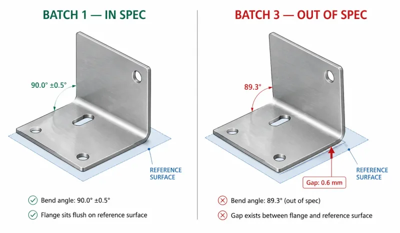
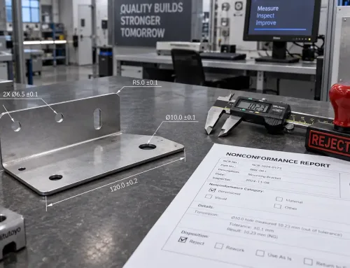
A side-by-side technical comparison showing two sheet metal flanges: the left panel shows a correct 90° bend angle (labeled “Batch 1 — In Spec”) with measurement value “90.0°”, and the right panel shows a drifted bend of approximately 89.3° (labeled “Batch 3 — Out of Spec”) with measurement value “89.3°”. Dimensional callouts and a red highlight on the gap caused by the angle deviation help the reader understand how a small angular drift of less than one degree can accumulate into assembly problems.
The enclosure may still look correct, but:
- The door no longer aligns
- A panel no longer fits
- Mounting holes shift
- Gaskets compress unevenly
- Internal hardware becomes difficult to install
Material Batch Variation
A different coil or sheet batch may behave differently from the material used for the approved sample.
Changes in ductility, hardness, grain direction, or surface condition may cause the same bending parameters to produce different results.
The supplier may compensate, but inconsistent adjustments can create variation within the same batch.
Coating Inconsistency
Powder coating consistency depends on controlled process parameters, including:
- Powder chemistry
- Pretreatment
- Oven temperature
- Curing time
- Line speed
- Spray distance
- Film thickness
- Grounding quality
If the order is treated as just another job on the coating line rather than a controlled production process, color, texture, gloss, adhesion, and coverage may vary between batches.
Each of these failures is preventable.
Each also costs far more to correct after production than to verify before production begins.
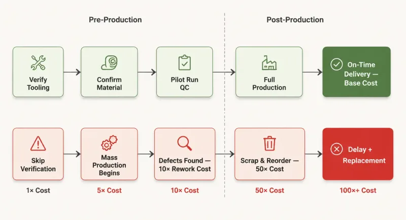
A simple left-to-right flowchart with two paths: the top path shows the low-cost route of verifying tooling, materials, and quality plans before production, leading to a green “On-Time Delivery” outcome. The bottom path shows the high-cost route of skipping verification, leading to red outcomes of rework, scrap, delivery delays, and replacement orders. Cost multipliers are shown at each failure step (e.g., “10× fix cost at production”). The design uses minimal text and clear visual hierarchy to communicate the economic argument at a glance.
OEM Metal Enclosure Production Readiness Checklist
Before authorizing full production, confirm the following items.
Drawings and Documentation
- Latest drawing revision is approved
- Revision history is available
- Critical dimensions are clearly marked
- Tolerances are defined
- Material grade and thickness are specified
- Surface finish requirements are documented
- BOM is complete
- Fastener and hardware locations are confirmed
- Assembly drawings are available where required
Materials
- Production material matches the approved sample
- Material source is confirmed
- Sheet thickness is verified
- Surface condition is acceptable
- Material certificates are available if required
- Batch variation risks have been reviewed
Tooling and Fixtures
- Press brake tooling is validated
- Bend radii match the approved design
- Bending sequence is documented
- Welding fixtures are validated
- Assembly jigs hold the correct positions
- Inspection gauges are available
- Tooling maintenance requirements are defined
Quality Control
- Critical dimensions are identified
- Inspection methods are defined
- Inspection frequency is documented
- Weld acceptance criteria are established
- Surface finish standards are confirmed
- Cosmetic defect limits are documented
- Non-conforming part procedures are agreed
Packaging and Logistics
- Protective packaging is defined
- Carton and pallet requirements are confirmed
- Labeling requirements are documented
- Delivery schedule is approved
- Inspection and rework buffers are included
- Shipping and handling risks are reviewed
Commercial and Acceptance Terms
- Acceptance criteria are attached to the purchase order
- Approved sample status is documented
- Pilot run quantity is agreed
- Rework responsibility is defined
- Replacement and credit procedures are confirmed
- Production approval is documented in writing