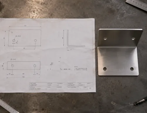
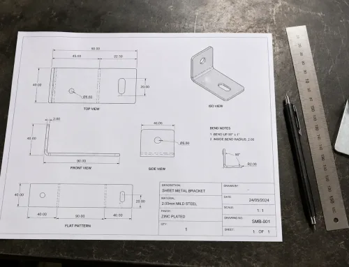
A design team sends a request for quote with a detailed 2D drawing — dimensions, tolerances, surface finish callouts, everything marked up clearly.
The manufacturer replies within a day: “Can you provide a 3D model?”
It is not that the drawing is wrong. It is that a 2D drawing alone does not give the manufacturer enough information to quote accurately or start production planning without significant back-and-forth.
This situation comes up more often than most designers expect.
If you are working with a custom sheet metal fabrication partner for the first time, understanding what a 3D model is in this context — and why it matters — can save days of communication and prevent quoting errors.
What Is a 3D Model in Sheet Metal Fabrication?
A 3D model is a digital, three-dimensional representation of a part created in CAD (Computer-Aided Design) software.
In sheet metal fabrication, it goes beyond a simple visual shape.
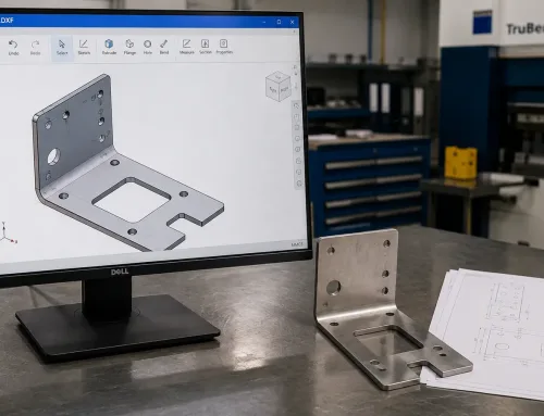
A production-relevant 3D model captures the part’s geometry — bends, flanges, cutouts, holes, and edge features — along with key manufacturing parameters such as material thickness, bend radius, and flange lengths.
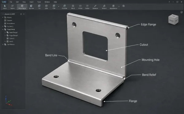
A fabrication-ready 3D CAD model of a sheet metal bracket with labeled annotations pointing to key geometric features: bend lines, flanges, cutouts, mounting holes, and edge reliefs.
Unlike a 3D model built for rendering or animation, a fabrication-ready model is parametric.
This means the dimensions are driven by parameters that maintain relationships between features.
When you change a bend radius, the flat pattern updates automatically.
When you adjust a flange length, the adjacent features stay in proper proportion.
This parametric behavior is what makes the model useful for manufacturing, not just visualization.
3D Model vs. 2D Drawing — What Each One Tells the Manufacturer
A 3D model and a 2D drawing for sheet metal fabrication serve different purposes. Neither one fully replaces the other.
A 3D model communicates geometry.
It shows the manufacturer exactly what the part looks like in three dimensions — where the bends are, how features relate to each other spatially, and how the flat blank transforms into the finished shape.
From a 3D model, the manufacturer can generate a flat pattern, check for tool access, and run DFM (Design for Manufacturability) analysis automatically.
A 2D drawing communicates intent.
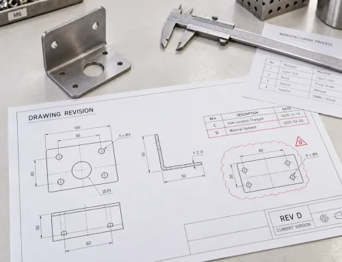
It carries information that a 3D model typically does not express well: geometric tolerances (GD&T), surface finish requirements, critical dimensions, material specifications, and notes about assembly or inspection.
A manufacturer quoting a precision enclosure needs the 3D model to understand the shape and the 2D drawing to understand what matters most.
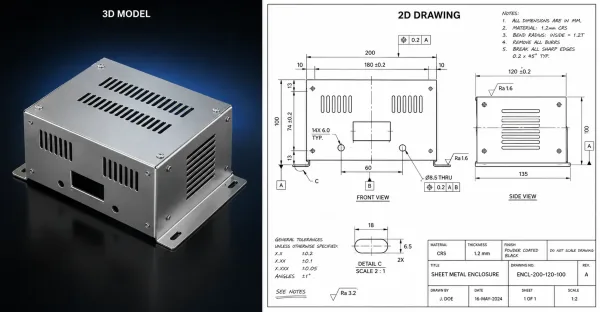
The left side shows a 3D CAD rendering of a precision sheet metal enclosure with visible bends and geometry, while the right side shows the corresponding 2D engineering drawing with GD&T callouts, dimensions, and surface finish notes.
The table below summarizes what each document provides:
| Information | 3D Model | 2D Drawing |
|---|---|---|
| Part geometry and spatial relationships | ✅ | Limited |
| Flat pattern generation | ✅ | ❌ |
| DFM and tool access checks | ✅ | ❌ |
| Geometric tolerances (GD&T) | ❌ | ✅ |
| Surface finish and material callouts | ❌ | ✅ |
| Assembly context and critical dimensions | ❌ | ✅ |
For most sheet metal RFQs, manufacturers expect both.
The 3D model drives quoting and production. The 2D drawing drives quality control and inspection.
What Happens After You Upload a 3D Model
When a manufacturer receives your 3D model, it does not go straight to the shop floor.
The file goes through several stages before manufacturing process planning can be completed and an accurate quote can be prepared.
First, the file is imported into the manufacturer’s CAM (Computer-Aided Manufacturing) software.
The software reads the geometry and identifies features — bends, holes, flanges, cutouts.
If the file format is incompatible or the model has errors (open surfaces, missing features, corrupt geometry), the process stops here.
The manufacturer contacts you for a corrected file.
Next, the model is reviewed for manufacturability.
The engineer checks whether bend radii are achievable with available tooling, whether hole-to-edge distances meet minimums, and whether the design can be produced without custom fixtures or secondary operations.
This is the sheet metal DFM review stage, and it often generates questions or suggestions sent back to the designer.
Then, if the model passes DFM review, the software generates a flat pattern — the unfolded shape of the part before bending.
This flat pattern determines material usage, nesting layout, and cutting path.
From here, the manufacturer can calculate material cost, machine time, and labor, and produce a quote.
Understanding this workflow explains why manufacturers prefer 3D models: each stage depends on accurate, machine-readable geometry that a 2D drawing cannot reliably provide.
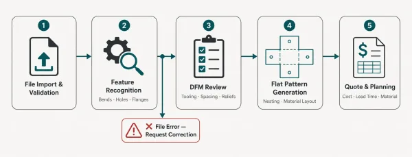
A horizontal process flow diagram illustrating the five key stages a 3D model goes through after being sent to a sheet metal manufacturer, from file import to final quotation.
File Formats That Work for Sheet Metal Fabrication
Not all 3D file formats are equal in a fabrication context.
Some preserve full parametric data; others only carry surface geometry with no feature history.
The table below shows the most common formats and how they fit sheet metal work:
| Format | Extension | Best For | Notes |
|---|---|---|---|
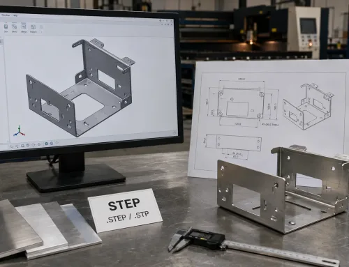
| STEP | .step, .stp | Universal exchange | Industry standard. Preserves solid geometry and is readable by all major CAD/CAM systems. Preferred for sheet metal quoting. |
| IGES | .iges, .igs | Legacy systems | Older format. Widely supported but may lose some parametric data during transfer. Acceptable as a backup. |
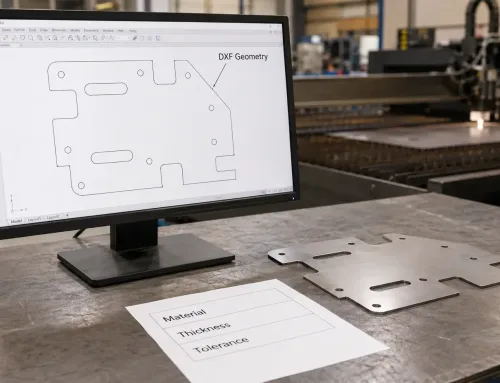
| DXF | .dxf | Flat 2D profiles | Works well for laser cutting of flat parts. Does not carry 3D bend information. |
| Native CAD | .sldprt, .f3d, .prt | Same-software workflows | Only usable if the manufacturer runs the same CAD software. Not recommended for cross-platform exchange. |
| STL | .stl | 3D printing, visualization | Mesh-based format. Not suitable for sheet metal fabrication — no feature data, no flat pattern capability. |
For most sheet metal RFQs, STEP is the safest choice.
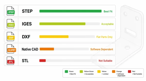
A visual comparison of five common CAD file formats — STEP, IGES, DXF, Native CAD, and STL — with green, yellow, and red indicators showing their compatibility with sheet metal fabrication workflows.
It is a vendor-neutral, ISO-standardized format that every serious fabrication shop can open and process.
If you use SolidWorks, Fusion 360, Inventor, or Creo, exporting to STEP takes less than a minute and avoids compatibility issues.
Production-Ready vs. Concept-Only Models
A 3D model can look correct on screen and still be unsuitable for manufacturing.
The difference lies in whether the model includes fabrication constraints or only visual geometry.
A production-ready model:
- defines material thickness as a consistent value,
- uses bend radii that match standard tooling,
- includes bend reliefs at transitions,
- and maintains minimum feature spacing.
It was built with sheet metal-specific tools in your CAD software — not modeled as a solid block and then hollowed out.
A concept model, by contrast, may represent the intended shape but lacks these manufacturing parameters.
It might use non-uniform wall thickness, sharp internal corners, or geometry that cannot be formed with standard press brake tooling.
The practical difference shows up during quoting.
A production-ready model can be processed automatically — the manufacturer imports it, generates a flat pattern, and produces a quote.
A concept model requires manual interpretation.
The manufacturer has to ask questions, make assumptions, or redesign the part before quoting.
This adds days to the process and introduces the risk of miscommunication.
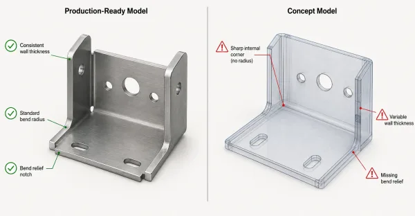
A comparison showing a production-ready sheet metal model with standard bend radii, consistent thickness, and proper reliefs on the left, versus a concept-only model on the right with red warning indicators highlighting non-uniform wall thickness, sharp corners, and missing bend reliefs.
If you are not sure whether your model is production-ready, check one thing:
Can your CAD software generate a valid flat pattern from it?
If the flat pattern looks correct — no overlapping geometry, no impossible bends — the model is likely suitable for fabrication.
What If You Do Not Have a 3D Model?
Not every project starts with a 3D model.
Some designers work from 2D drawings, sketches, or even physical samples.
Most manufacturers can work with these, but the process is different.
If you have a 2D drawing with complete dimensions, many manufacturers can create a 3D model from it as part of the quoting process.
This is common for simpler parts — brackets, flat panels, basic enclosures.
The manufacturer models the part, generates the flat pattern, and quotes from that.
For complex parts with many bends or tight tolerances, having the designer provide the 3D model is faster and reduces the chance of errors during translation.
If you have only a sketch or a concept, some manufacturers offer design assistance.
They can help you develop a manufacturable 3D model based on your requirements.
This service typically involves a design review meeting where the manufacturer’s engineer walks through the geometry, material selection, and DFM considerations with you.
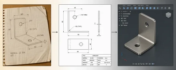
A three-stage visual progression showing how a concept sketch is first translated into a 2D engineering drawing with dimensions, and then built into a 3D fabrication-ready CAD model — illustrating that manufacturers can work from different starting points.
The key is to share as much information as you have — dimensions, material, quantity, surface finish, and intended application.
Even without a 3D model, a well-prepared 2D drawing with clear callouts gives the manufacturer a strong starting point.