
A DFM review sounds like a paperwork check—until a design that looks complete on paper stalls in the shop, doubles in the quote, or fails at first article. The real question is not whether the drawing is finished. It is whether the part can be manufactured reliably and economically as designed.
Why People Confuse DFM Review with Drawing Review
Engineering teams often treat DFM review and drawing review as the same meeting. They are not.
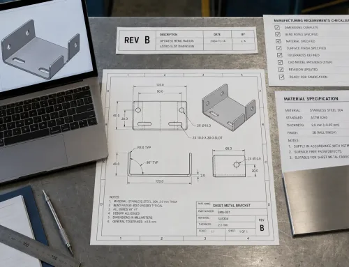
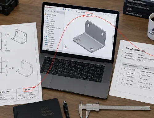
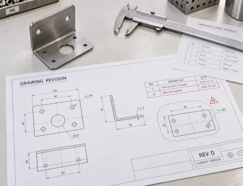
A drawing review asks: Is the documentation complete and consistent? Dimensions, datums, title block, revision level, material callouts, and notes are present and unambiguous.
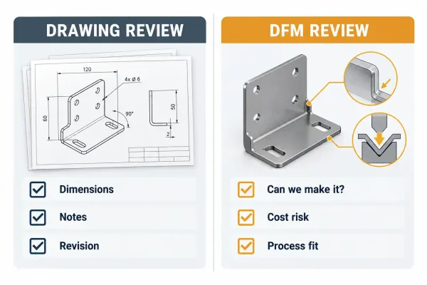
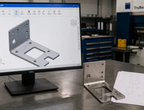
Drawing review asks if documentation is complete. DFM review asks if the part can be made well and economically.
A DFM review asks a different question: Can this design be made well, repeatably, and at an acceptable cost with the intended process? A drawing can be fully annotated and still be expensive, fragile, or slow to produce.
That gap is where projects lose time. Purchasing sends a “complete” package to a fabricator. The fabricator quotes it, then flags half a dozen features that force extra setups, special tooling, or tighter inspection. None of that is a drawing error. It is a manufacturability problem.
Drawing review reduces interpretation risk. DFM review reduces production and cost risk. You need both, in that order of priority when the design is still flexible.
What a DFM Review Actually Is
A DFM review (design for manufacturability review) is a structured assessment of a product design against manufacturing process capability. The goal is to identify features that will be difficult, inconsistent, or costly to produce—and to recommend changes before those features are locked into tooling, purchase orders, or production schedules.
In practice, the review is also called a manufacturability review or DFM analysis. The name matters less than the output: ranked findings and specific design recommendations, not a generic “looks good.”
For custom sheet metal work, the assessment covers how the flat pattern becomes a finished part: cutting, forming, joining, finishing, and inspection. It judges fit to process limits—not aesthetic preference, and not whether every note is on the print.
A useful DFM review is done by people who will make the part, or by engineers who know the process limits in detail. Software flags some issues. Experienced fabricators flag the ones that actually move cost and lead time.
What “Suitable for Manufacturing” Means for a Sheet Metal Part
“Manufacturable” is not a binary label. For sheet metal, it means each feature stays within practical process capability without unusual effort. The checks below are the core of that judgment.
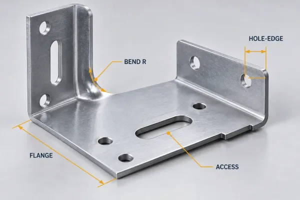
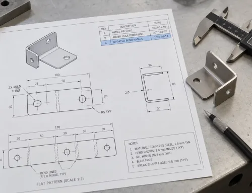
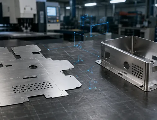
Core manufacturability checks on a sheet metal part: bend radius, hole-to-edge, flange length, and assembly access.
Cutting and Flat-Pattern Feasibility
Laser, punch, and waterjet all cut profiles efficiently when geometry is clean. Open contours, duplicate lines, micro-slivers, and extremely narrow webs slow nesting and can leave weak sections that distort during forming. Internal cutouts closer than roughly one material thickness to a bend line often crack or oil-can after forming unless the layout is revised.
Forming and Bend Geometry
Bend radius, flange length, and bend sequence drive formability. Inside radii tighter than about one material thickness (for mild steel; closer to 1.5× for stainless and aluminum in many shops) invite cracking or unpredictable springback. Flanges shorter than the die opening plus radius leave nothing for the press brake to register against. Multiple bends on the same plane, or bends that require the part to be flipped repeatedly, add setups and stack error.
Holes, Slots, and Thin-Wall Limits
Hole diameter smaller than material thickness, holes closer than about 2× thickness to an edge or bend, and elongated slots with sharp ends are common failure points. Threaded holes in thin sheet need enough engagement—often a fastener insert rather than tapped parent material. Any of these is manufacturable; each has a preferred method and a cost implication if left as a “default” CAD feature.
Joining and Assembly Access
Welded corners, PEM hardware, rivets, and brackets all need access: torch angle, welder reach, press tooling clearance, or driver clearance. A design that is geometrically sound but impossible to fixture or weld without grinding is not DFM-clean. Joint type also drives cost—continuous seam welds cost more than spot welds or folded corners when strength and sealing allow it.
Surface Finish Compatibility
Coatings and anodize add thickness. Powder coat typically builds 0.05–0.10 mm per face. If mating parts must slide or seal, that buildup must be in the tolerance model—or the DFM review will flag fit failures that appear only after finishing. Masking, no-scratch zones, and post-weld finishing add process steps that should be intentional, not accidental.
Which Design Features Create Cost and Lead-Time Risk
DFM review should connect geometry to money and schedule. The features below consistently move quotes upward.
| Design feature | Why it raises cost or lead time | Typical DFM direction |
|---|---|---|
| Overly tight tolerances (e.g. ±0.1 mm on non-fit dims) | Forces slower cutting, extra forming checks, or selective inspection | Relax to process capability; keep tight only on fit-critical dims |
| Non-standard hole sizes or patterns | Extra tool changes, custom punches, or laser-pierce time | Match standard tooling and common fastener sizes |
| Dense or multi-plane bends | More setups, higher springback scrap, stack-up risk | Reduce bends per part; group bends on one plane where possible |
| Welded assemblies that could be folded or fastened | Weld labor, distortion control, post-weld grinding | Prefer folded corners or hardware when strength/sealing allow |
| Heavy finishing on tight-tolerance features | Masking, thickness buildup, rework after coat | Design clearance for finish; specify mask only where required |
| Multiple material thicknesses in one assembly | Different tooling, nesting, and weld settings per piece | Standardize thickness across parts where structure allows |
Cost risk is rarely one dramatic feature. It is the accumulation of “small” choices—each legal on the drawing, each adding time on the floor.
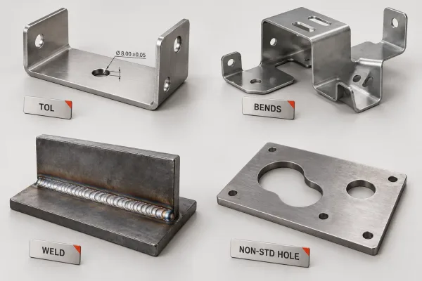
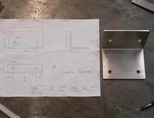
Design features that quietly raise sheet metal cost and lead time: tight tolerances, extra bends, avoidable welds, and non-standard holes.
How Tolerances, Geometry, and Process Choices Interact
Tolerance is not an isolated number. It is a contract with the process that will hold it.
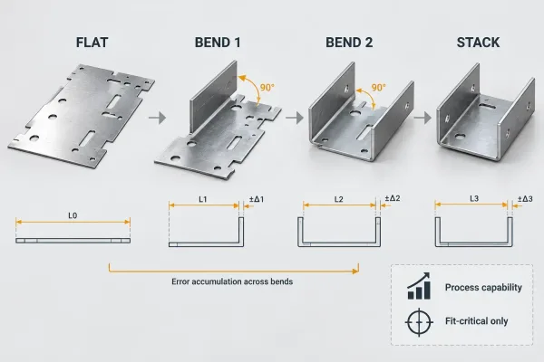
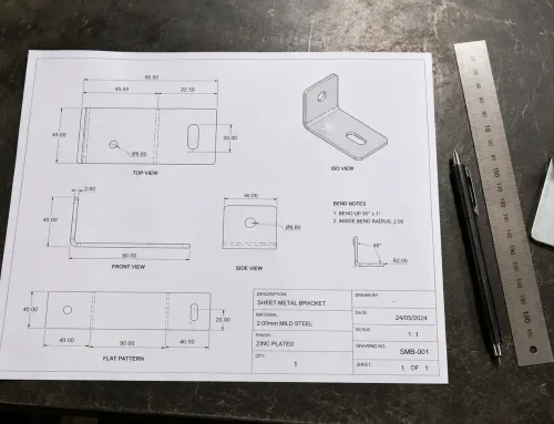
Tolerance must match the process that will hold it; tight callouts across bends stack error and inspection cost.
Laser cutting on mild steel commonly holds about ±0.1 mm on external profiles; press brake angles vary with material springback, length, and tooling wear. A ±0.5° angle callout on a long flange may be unachievable without dedicated tooling and extra checks. The DFM review should ask: Does this tolerance match the process that will run the part, and does it control something the function actually needs?
Geometry amplifies the issue. A tight position tolerance across two bends stacks bend angle error and flat-pattern error. Tight hole-to-bend distances force sequencing that reduces how much error can be absorbed. When every dimension is “critical,” nothing is—inspection time rises and yield falls.
Process choice then feeds back. If the design allows punch instead of laser for a high-volume blank, unit cost drops. If a fold replaces a weld, distortion risk drops. The review’s job is to surface those trade-offs while the model can still change.
What a Useful DFM Review Delivers
A useful review is not a verbal “looks fine.” It produces artifacts engineering and purchasing can act on:
- Impact-ranked findings — issues ordered by effect on cost, lead time, or quality, not by when someone happened to notice them
- Specific change requests — “increase inside radius to 1× thickness” or “move hole 3 mm off the bend line,” not “review geometry”
- Acceptable deviations — where process capability is slightly outside the print and function still holds, the review should say so and recommend a revised callout
- Open questions — real ambiguities (finish after weld? which surface is cosmetic?) listed before RFQ, not discovered in the first-article report
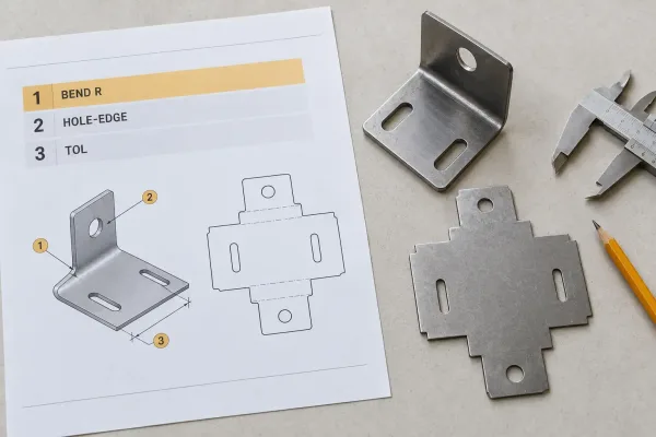
A useful DFM review delivers impact-ranked findings and specific change requests engineering and purchasing can act on.
Purchasing uses the same package to avoid rework loops: fewer clarification emails, fewer re-quotes after “impossible” features surface late, cleaner apples-to-apples supplier comparison. Engineers get a short list of changes that protect function without locking in factory-specific pain.
When to Run a DFM Review
Timing changes value.
Before design freeze is ideal. Changes are still CAD edits. Cost impact is highest here—fixing a bend layout in the model is free compared to fixing it after soft tooling is cut.
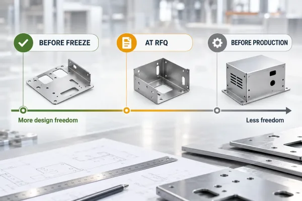
Run a DFM review before design freeze or at RFQ; the later it happens, the less freedom remains to change the part.
At RFQ is the practical minimum for custom sheet metal. Send the package, request a manufacturability check with the quote, and treat findings as design input—not as the supplier being “difficult.”
Before production or first article still helps, but the freedom is lower. At that stage the review focuses on process control, inspection points, and whether sample results will transfer to volume.
Prototype and production emphasis differs. Prototypes prioritize speed and feature proof; some DFM issues can be accepted temporarily. Production prioritizes repeatability, fixture stability, and cost per piece. A design that barely works in a one-off may fail at 500 pieces.
FAQs