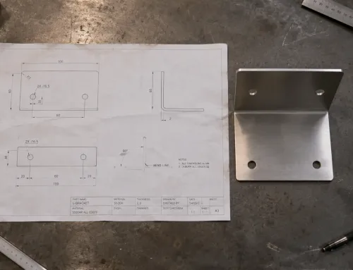
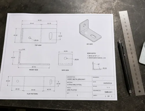
You finish a sheet metal bracket in SolidWorks, export the native .SLDPRT file, and send it to a contract manufacturer for quoting. A few hours later, an email arrives: “We cannot open this file. Can you provide a STEP or DXF instead?”
This scenario plays out daily across engineering and procurement teams. The root cause is not a technical failure—it is a format mismatch. Every CAD software saves files in its own proprietary structure, and most manufacturers run different software than their customers. A file that opens perfectly on your screen may be unreadable on the other end.
Understanding CAD file formats is not just a technical curiosity. For engineers and buyers working with external manufacturers, preparing a complete sheet metal RFQ—including the right CAD format—directly affects how fast you get a quote and how accurately your parts are produced.
What Is a CAD File?
A CAD file is a digital document created by Computer-Aided Design software that stores the geometry, dimensions, and design parameters of a part or assembly. Engineers and designers use CAD files to define what a part looks like before it is manufactured.
CAD files come in two broad categories. 2D CAD files contain flat drawings—outlines, dimensions, and annotations typically used for drafting and shop-floor documentation. 3D CAD files contain solid or surface models that represent the full geometry of a part in three dimensions. Modern sheet metal fabrication workflows rely heavily on 3D models for programming CNC machines, laser cutters, and press brakes, while 2D drawings remain the primary vehicle for conveying tolerances, materials, and finishing requirements.
Three Types of CAD File Formats

A clean technical comparison diagram showing three columns labeled “Native,” “Exchange,” and “Mesh,” each with representative file format icons and a sample 3D model showing the level of detail each format preserves.
Not all CAD files are interchangeable. They fall into three categories, each with distinct trade-offs.
Native (Proprietary) Formats
Native formats are created and read only by the software that produced them. Examples include .SLDPRT (SolidWorks), .CATPart (CATIA), .IPT (Autodesk Inventor), and .DWG (AutoCAD). These files retain the complete design history—feature trees, parametric relationships, and sketch constraints. They are ideal for iterative design work within a single software environment.
The limitation is obvious: a native file is locked to its parent software. If your manufacturer does not run the same CAD platform, they cannot open it.
Exchange (Neutral) Formats
Exchange formats are designed to move 3D geometry between different CAD systems. The most widely used is .STEP (.stp or .step), governed by the ISO 10303 standard. STEP files carry complete 3D geometry with high fidelity, making them the de facto standard for sharing models with external manufacturers, simulation tools, and supply chain partners.
.IGES (.igs) is an older exchange format still found in legacy workflows. .DXF (.dxf), originally developed by Autodesk, is a neutral format primarily used for 2D profiles and is the standard input for laser cutting and CNC punching machines.
Exchange formats sacrifice the parametric feature history—manufacturers see the final geometry but cannot edit individual features like a fillet or a hole pattern. For quoting and production, this is rarely a problem.
Mesh Formats
Mesh formats represent 3D surfaces as a collection of triangles. .STL is the most common mesh format, widely used in 3D printing and rapid visualization. .OBJ and .3MF serve similar purposes.
Mesh files are lightweight and universally readable, but they contain no engineering data—no dimensions, no tolerances, no material information. A mesh file tells a manufacturer the shape of a part, but nothing about how to make it.
| Format Type | Examples | Geometry Fidelity | Engineering Data | Parametric History |
|---|---|---|---|---|
| Native | .SLDPRT, .CATPart, .IPT, .DWG | Full | Full (within software) | Yes |
| Exchange | .STEP, .IGES, .DXF, .JT | High | Partial (geometry only) | No |
| Mesh | .STL, .OBJ, .3MF | Surface only | None | No |
Common CAD File Formats and What Each One Does
.DWG and .DXF — The 2D Drafting Standard
.DWG is AutoCAD’s native format and the most widely used file type for 2D engineering drawings. It stores lines, dimensions, hatching, and text annotations. While DWG is technically a native format, its ubiquity means most CAD software can read or import it.
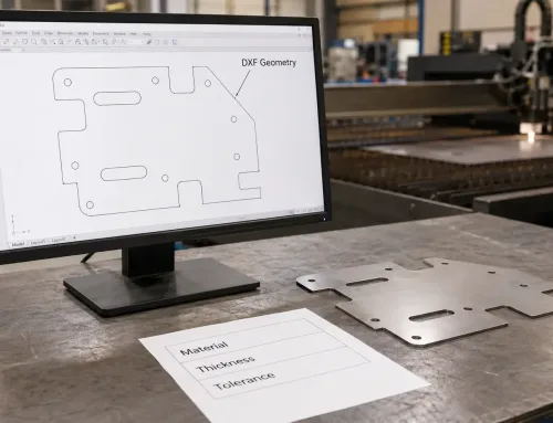
.DXF is the exchange equivalent of DWG—a neutral 2D format that any software can open. In sheet metal manufacturing, DXF files are the standard input for laser cutting, waterjet, and CNC punching because they carry clean 2D profiles that cutting machines can interpret directly.
.STEP — The Universal 3D Exchange Format
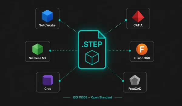
A diagram showing a single STEP file in the center connecting outward to multiple CAD software platforms, illustrating its role as a universal exchange format.
.STEP (.stp / .step) is the most important format for engineers sharing 3D models with external parties. Governed by ISO 10303, STEP is an open standard—not controlled by any single software vendor.
When you send a STEP file to a manufacturer, they can open it in SolidWorks, CATIA, Siemens NX, Fusion 360, or virtually any modern CAD system. The geometry transfers accurately. What you lose is the feature history and parametric relationships, but for manufacturing purposes, the final shape is what matters.
.IGES — The Legacy Exchange Format
.IGES (.igs) predates STEP and is still encountered in older supply chains, particularly in aerospace and defense. It transfers surface and wireframe geometry reliably but has known limitations with complex solid models.
If your customer or supplier specifically requests IGES, STEP is almost always a better alternative—ask whether they can accept STEP instead.
.STL — For 3D Printing, Not for Manufacturing
.STL files describe a surface as a mesh of triangles. They are the standard input for 3D printing and are useful for quick visual review.
However, STL files contain no dimensional data, no tolerances, and no material specifications. Sending an STL to a sheet metal manufacturer is like sending a photograph of a blueprint—it shows the shape but provides none of the information needed to produce the part.
.SLDPRT / .CATPart / .IPT — Software-Specific Formats
These native formats are the working files inside their respective CAD systems. They are the best choice when both you and your manufacturer use the same software, since they preserve the complete design intent.
In practice, most cross-company workflows convert to STEP before sharing.
What to Send a Sheet Metal Manufacturer
Why STEP + PDF Drawing Is the Best Combination for Quoting
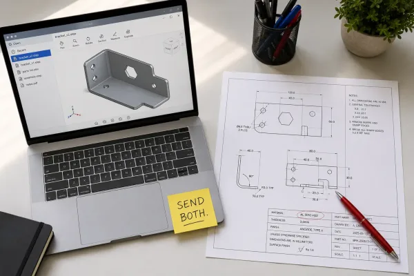
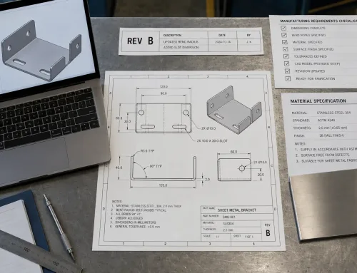
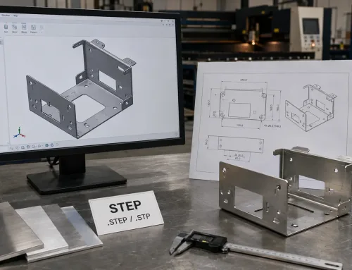
An overhead view of a desk showing a laptop screen displaying a STEP file in a CAD viewer, next to a printed PDF engineering drawing with annotations, representing the ideal file package for requesting a manufacturing quote.
For most sheet metal quoting scenarios, the ideal submission is a STEP file of the 3D model paired with a 2D fabrication drawing in PDF format that specifies material, thickness, tolerances, surface finish, and any secondary operations (welding, tapping, plating).
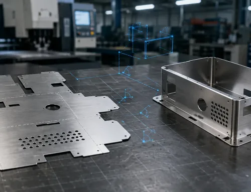
The STEP file gives the manufacturer the geometry they need to program laser paths, bend sequences, and fixture layouts. The PDF drawing gives them the engineering requirements the model alone cannot carry.
A STEP file without a drawing forces the manufacturer to make assumptions about material, tolerances, and finish—assumptions that often lead to clarification emails, delayed quotes, or parts that do not meet your expectations.
When DXF Is the Right Choice
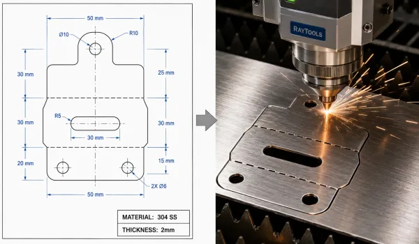
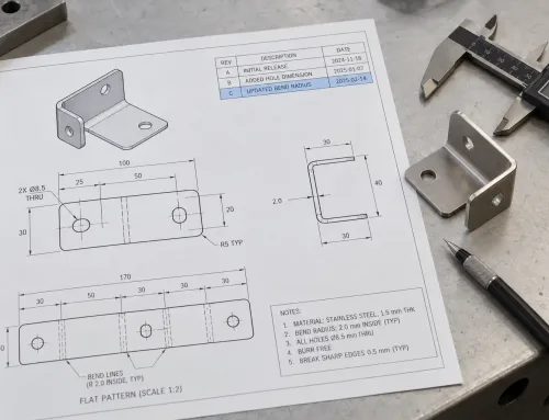
A split image showing a 2D DXF drawing of a flat sheet metal bracket profile on the left, and an industrial laser cutter actively cutting a metal sheet on the right, illustrating the direct workflow from DXF to production.
For flat-profile work—precision laser cutting, waterjet cutting, or CNC punching—a 2D DXF file is often all that is needed. The DXF carries the cut profile, and the manufacturer pairs it with your specifications for material and thickness.
If your part only requires cutting (no bending, no welding, no assembly), DXF is simpler and more direct than a 3D model.
What the File Needs to Contain
Regardless of format, every file you send to a manufacturer should include or be accompanied by:
- Units — millimeters or inches. A model built in inches sent to a manufacturer working in millimeters will produce parts that are 25.4× the intended size.
- Material specification — not just “steel” but a specific grade (e.g., ASTM A36 cold-rolled steel, 304 stainless, 5052-H32 aluminum).
- Sheet thickness — the nominal thickness of the raw material. For sheet metal, this is a critical dimension that affects bend calculations and structural performance.
Why the Model Is Not the Manufacturing Specification
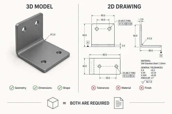
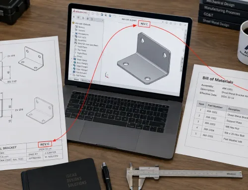
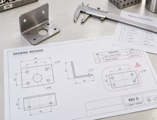
A side-by-side comparison showing a 3D CAD model of a sheet metal bracket on the left and a 2D engineering drawing with GD&T callouts, material specifications, and surface finish symbols on the right, demonstrating that both are needed for manufacturing.
A common misconception among first-time buyers is that the 3D model is the complete manufacturing instruction. It is not.
A CAD model defines geometry—the shape, size, and spatial relationships of features. It does not tell a manufacturer what material to use, what tolerances to hold, what surface finish to achieve, or how to handle sharp edges and weld seams.
The manufacturing specification lives in the technical drawing for manufacturing. This is where GD&T (Geometric Dimensioning and Tolerancing), material callouts, surface roughness symbols, critical dimensions, and notes about finishing or inspection are recorded.
In a well-run manufacturing workflow, the model and the drawing work together: the model provides the shape, the drawing provides the requirements. Sending only a model is like giving someone a map without telling them the destination—they can see the roads but do not know where to go.
How to Open and View CAD Files Without AutoCAD
Not everyone who receives a CAD file needs—or can afford—a full CAD license. For buyers, project managers, and quality inspectors who only need to view, measure, or annotate a model, free viewers are widely available.
Autodesk Viewer (viewer.autodesk.com) is a browser-based tool that opens DWG, STEP, IGES, DWF, and other common formats with no software installation. eDrawings Viewer (free from Dassault Systèmes) opens SolidWorks, STEP, DXF, and DWG files and allows basic measurement and markup. FreeCAD is an open-source parametric CAD program that can import and view STEP, IGES, and STL files, though its interface has a steeper learning curve. For quick 3D visualization of STEP or STL files, browser-based viewers like ShareCAD or 3D Viewer Online require no installation at all.
For most buyer-side workflows, a free viewer is sufficient. You do not need to own a CAD license to review a manufacturer’s proposal or verify that a received model matches your expectations.
Making Sure Your CAD File Is Ready for Quoting
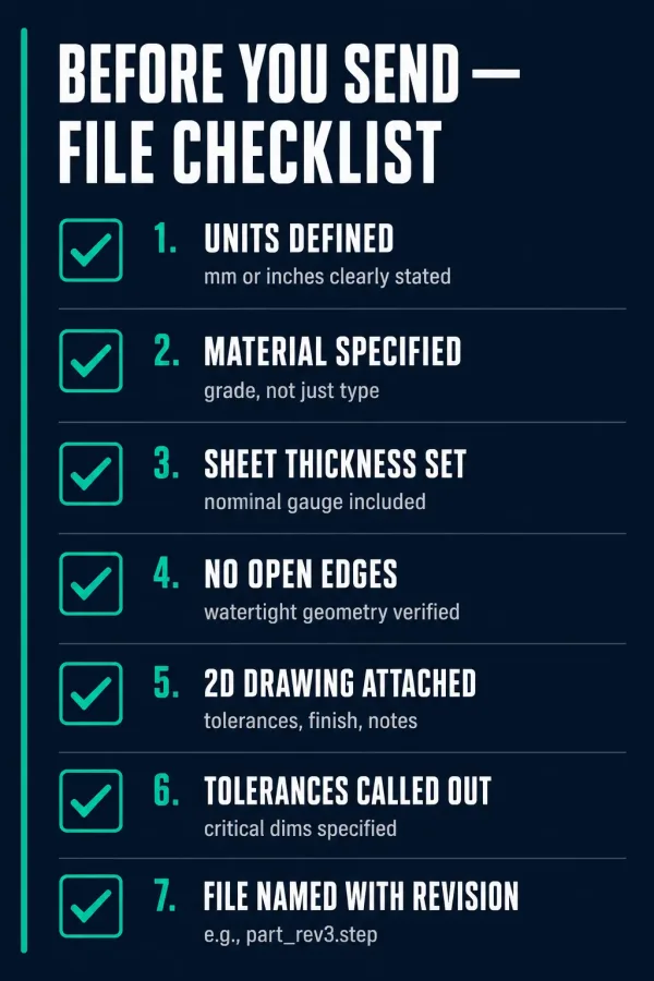
A clean checklist-style infographic listing the key items engineers should verify before sending CAD files to a manufacturer for quoting, including units, material, thickness, tolerances, and file naming.
Before you send files to a manufacturer, run through this checklist. Each item addresses a common source of delays, miscommunication, or rejected quotes.
- Sheet thickness is defined in the model or drawing. A zero-thickness surface model cannot be quoted for sheet metal—the manufacturer needs to know the raw material gauge.
- Units are correct and clearly stated. Do not assume the recipient uses the same unit system.
- No open edges or missing faces. A model with gaps in the surface geometry will fail import or require manual repair, adding days to the quoting process.
- A 2D drawing accompanies the 3D model. The drawing should specify material, tolerances, surface finish, and any secondary operations.
- Tolerances are explicitly called out for critical dimensions. If you do not specify tolerances, the manufacturer will apply their standard—which may or may not match your requirements.
- Surface treatment is specified (e.g., powder coat, anodize, zinc plate, or none). Leaving this blank means the manufacturer will quote raw, untreated parts.
- File names are clear and include a revision number. “bracket_final_v3.step” is better than “bracket.step” when multiple revisions are in circulation.
Summary
- CAD files come in three types—native, exchange, and mesh. For sharing with manufacturers, STEP (3D) and DXF (2D) are the most reliable exchange formats.
- A 3D model is not a manufacturing specification. Always pair your model with a 2D drawing that specifies material, tolerances, and finish requirements.
- A few minutes of file preparation saves days of back-and-forth. Use the quoting checklist above to make sure your submission is complete before it reaches the manufacturer.