A drawing can carry an approval stamp and still produce the wrong part.
The stamp may be on an outdated revision. A reviewer may have written “approved as noted” while a critical dimension comment remains unresolved. The 2D drawing may be updated while the flat pattern or CNC file still reflects the earlier geometry.
In each case, the visible approval is real — but the production release is not controlled.
In sheet metal fabrication, drawing approval is not a single sign-off moment. It is a traceable chain that runs from the first engineering review through customer confirmation to a final production release gate.
Understanding what each link in that chain does — and where it can break — is the difference between a smooth production run and a batch of parts that meet the stamp but miss the intent.
The Approval Stamp Does Not Mean the Drawing Is Production-Ready
Many engineers and procurement teams treat drawing approval as the finish line. Once the customer signs off, production can begin.
In practice, approval is a midpoint checkpoint, not a starting signal.
Approval means the reviewer has verified that the drawing is consistent with the design intent and the contractual requirements within their assigned scope.
It does not mean the drawing is complete enough to enter production.
Between approval and production release, several conditions still need to be confirmed:
- The approved revision must match the version actually released to the shop floor
- All reviewer comments must be incorporated and closed — not just noted
- Downstream files (flat patterns, CNC programs, bend sequences) must reflect the approved geometry
- Obsolete drawing issues must be withdrawn so no one works from an old version
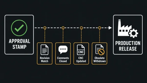
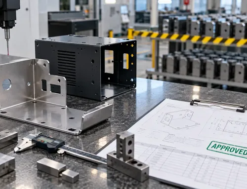
A visual breakdown of the four conditions that must be confirmed between drawing approval and production release: revision matching, comment closure, downstream file updates, and obsolete document withdrawal.
This distinction matters because the cost of catching an error after production starts is exponentially higher than catching it during approval.
A dimensional error found during the approval stage costs a few hours of revision time. The same error found after a batch of 500 parts is laser-cut and bent costs scrap, rework, and schedule delays.
Who Approves the Drawing — And What Each Role Actually Controls
Drawing approval in sheet metal fabrication typically involves multiple parties, each with a defined scope of responsibility.
The table below shows the most common roles and what each one actually controls.
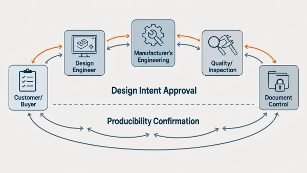
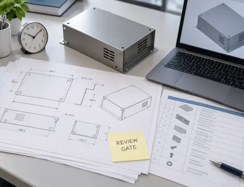
The five key roles in the sheet metal drawing approval process — customer, design engineer, manufacturer’s engineering team, quality/inspection, and document control — each with defined responsibilities spanning design intent and producibility.
| Role | Core Responsibility | What They Approve |
|---|---|---|
| Customer / Buyer | Defines functional requirements, tolerances, and material specifications | Final sign-off on design intent and commercial terms |
| Design Engineer | Creates the 3D model and 2D drawing | Geometric accuracy, dimensioning scheme, tolerance callouts |
| Manufacturer’s Engineering Team | Reviews drawings for manufacturability (DFM) | Feasibility of bends, cuts, hole placements, and surface finishes within shop capabilities |
| Quality / Inspection | Defines inspection criteria and measurement methods | Whether critical dimensions are measurable and inspectable |
| Document Control | Tracks revisions, transmittals, and distribution | That the correct revision reaches every user and obsolete issues are withdrawn |
The customer’s approval confirms design intent. The manufacturer’s engineering review confirms producibility.
These are two different decisions, and neither should be assumed from an informal email or a verbal “looks good.”
In practice, the most efficient approval workflows happen when the customer and manufacturer’s engineering team review the drawing in parallel — not sequentially.
When the manufacturer’s DFM feedback and the customer’s design review happen at the same time, issues are caught earlier and the total approval cycle is shorter.
What a Typical Drawing Approval Workflow Looks Like in Sheet Metal Fabrication
The approval workflow in sheet metal fabrication follows a predictable sequence, though the exact steps vary by project complexity and customer requirements.
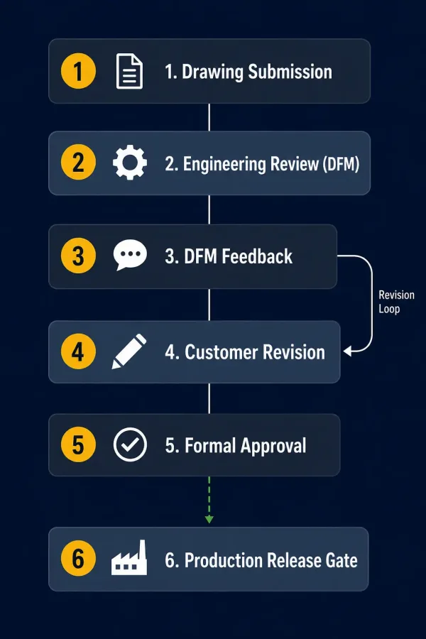
A step-by-step flowchart of the typical sheet metal drawing approval workflow, highlighting the revision loop between DFM feedback and customer revision before reaching formal approval and production release.
Step 1: Drawing Submission
The customer or their design engineer submits the drawing package — typically a 3D model (STEP or IGES) and a technical drawing with dimensions, tolerances, material callouts, and surface finish specifications.
Step 2: Engineering Review (DFM Check)
The manufacturer’s engineering team performs a sheet metal DFM review to confirm that the drawing can be manufactured reliably.
This is not a rubber stamp.
The review checks whether the sheet metal bending requirements, including bend radii, are achievable with available tooling, whether hole-to-edge distances meet minimums, whether tolerances are tighter than necessary, and whether the material specification is complete.
If the drawing uses a callout like “bend per standard” without specifying radius or angle, the engineering team flags it for technical clarification.
Step 3: DFM Feedback
The manufacturer sends back a DFM report — a list of questions, suggested changes, or concerns.
Common items include missing bend relief, undersized flanges, ambiguous tolerance zones, or surface finish specifications that conflict with the chosen material.
Step 4: Customer Revision and Confirmation
The customer reviews the DFM feedback, revises the drawing if needed, and confirms the updated version.
This is the point where many approval cycles stall — not because of technical complexity, but because of slow response times or unclear communication about which comments require action and which are informational.
Step 5: Formal Approval
Once both sides agree the drawing is complete and producible, the customer assigns a formal approval status.
This status determines whether the drawing can proceed to production release.
Step 6: Production Release Gate
After approval, the manufacturer confirms that:
- The correct revision is loaded into production systems
- All downstream files are updated
- The shop floor is working from the controlled issue
Only after this quality control and inspection process is complete does production begin.
Approval Statuses and What They Mean for Your Timeline
Not all approvals carry the same weight.
The status assigned to a drawing determines whether production can start, whether revisions are needed, or whether the submission is rejected outright.
| Status | Meaning | Effect on Production | Typical Timeline Impact |
|---|---|---|---|
| Approved | The reviewer accepts the submitted revision within their assigned scope | Eligible for production release gate | No delay — proceeds to release verification |
| Approved as Noted | The reviewer accepts the drawing subject to incorporating identified notes | Production may start only after noted corrections are incorporated | Minor delay (hours to 1–2 days) depending on correction complexity |
| Revise and Resubmit | The submission is not accepted for production | Full hold — revised drawing must be resubmitted for review | Moderate delay (days to a week) depending on revision scope |
| For Review | Formal submission awaiting authorized review | No release — pending review decision | Delay depends on reviewer turnaround time |
The most common source of confusion is “Approved as Noted.”
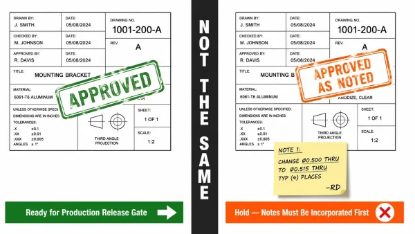
A comparison showing that “Approved” allows production release verification while “Approved as Noted” requires corrections to be incorporated before production can proceed — two statuses that are often confused.
Some teams treat it as a green light to start production.
It is not.
It means the reviewer has conditional acceptance — the notes must be incorporated before the drawing is truly production-ready.
If the notes are ignored or deferred, the resulting parts may not match the reviewer’s intent.
For procurement teams managing delivery schedules, the practical question is: how long does each status add to the lead time?
A drawing that arrives “Approved” adds zero days.
A drawing that arrives “Revise and Resubmit” can add a full review cycle — typically 3 to 7 business days depending on the complexity of the revisions and the responsiveness of both parties.
Why Drawings Get Sent Back — Common Reasons for Approval Failure in Sheet Metal
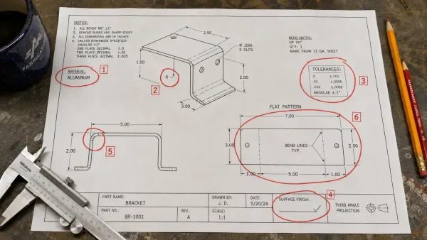
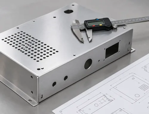
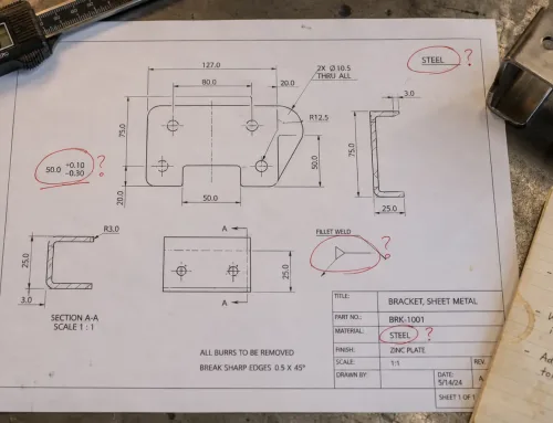
Six common issues that cause sheet metal drawing approval failures — incomplete material specification, missing bend information, unnecessary tight tolerances, no surface finish callout, missing bend relief, and inconsistent flat pattern — highlighted on an engineering drawing.
Drawing approval failures in sheet metal fabrication are rarely caused by dramatic design errors.
They are usually caused by missing or ambiguous information that forces the manufacturer to guess — and guessing in manufacturing leads to wrong parts.
The most common reasons drawings are sent back for revision:
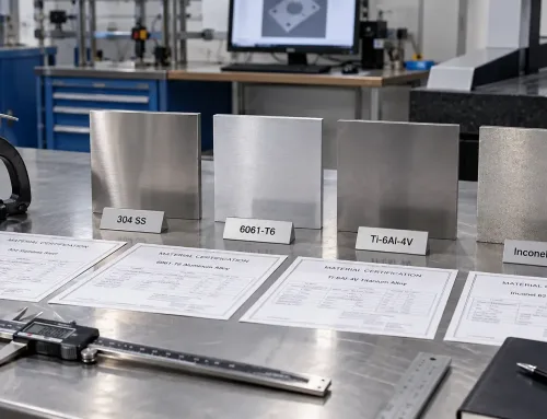
- Incomplete sheet metal material specification. Calling out “steel” or “aluminum” without specifying the alloy, temper, and thickness. “Aluminum” could mean 5052-H32, 6061-T6, or 3003-H14 — each with different bendability, strength, and cost.
- Missing or ambiguous bend information. Specifying bend angles without bend radii, or using “bend per standard” without defining what standard applies. Bend radius directly affects springback, tooling selection, and whether the part can be formed without cracking.
- Tolerances tighter than necessary. Defaulting to ±0.1 mm on every dimension when only critical interfaces need that precision. Tighter tolerances increase cost and inspection time — and when they appear on non-functional features, the manufacturer questions whether the designer understands the manufacturing process.
- Missing sheet metal surface requirements. Leaving the surface finish open or writing “finish per drawing” without actually specifying a finish. Powder coating, anodizing, and brushing each require different preparation steps and affect dimensional tolerances.
- Missing bend relief or corner relief. Small features near bends that cause cracking or distortion during forming. These are easy to add in CAD but expensive to fix after cutting.
- Flat pattern not provided or inconsistent with the formed drawing. When the 2D drawing shows formed dimensions but the flat pattern is missing or contradicts the bend callouts, the manufacturer cannot program the laser or press brake with confidence.
The pattern behind most approval failures is simple: the designer assumed the manufacturer would infer the missing information.
In sheet metal fabrication, inference is the enemy of precision.
The more clearly the drawing communicates key sheet metal design requirements such as material, tolerances, bend parameters, and surface finish, the faster it passes approval — and the more likely the finished part matches the design intent.