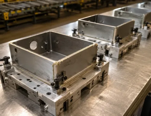
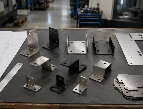
A progressive die for an automotive bracket might go through five to eight correction loops before it produces a part that passes dimensional inspection. A simple flat blanking die might need only one.
The difference is not luck — it is the tryout process, and how well each correction loop is executed determines whether the die enters production with confidence or with risk.
Die tryout is often treated as a final checkbox in the tooling development timeline. The die is built, it goes on the press, parts come out, someone signs off.
In reality, tryout is an iterative engineering validation where the die is tested, measured, corrected, and re-tested under real production conditions.
The goal is not to produce one acceptable part — it is to prove the die can produce acceptable parts consistently, shift after shift, at the tonnage and speed that production demands.
What Die Tryout Actually Validates
Die tryout is sometimes described as “running the first parts,” but that understates what is actually being evaluated.
A structured tryout validates three things simultaneously: the die, the process, and the part.
The die itself must operate correctly — upper and lower halves align, cutting clearances are uniform, forming surfaces make proper contact, and all moving components (strippers, lifters, pressure pads) function without binding or excessive wear.
The process must be stable — strip feeding is reliable, part transfer between stations is consistent, cycle time is achievable, and press tonnage stays within safe limits.
And the part must meet specification — dimensions, surface quality, forming integrity, and repeatability across multiple runs.
If any one of these three dimensions fails, the die is not ready for production.
A part that looks correct but varies by 0.3 mm between runs is a process problem.
A die that produces good parts at low speed but marks the surface at production speed is a die problem.
Tryout is where these distinctions become visible.
The Tryout Sequence — From Press Setup to Signed-Off Samples
A complete tryout follows a structured sequence.
Skipping steps or rushing through them is the most common cause of late-stage rework.
Press Setup and First Stroke
The die is installed on the tryout press, which should match the target production press as closely as possible — same tonnage capacity, stroke length, bed size, and cushion type.
Press settings (shut height, cushion pressure, stroke speed) are adjusted to establish a baseline.
The first stroke is run at reduced speed to verify basic die function — no interference, no abnormal force spikes, no misalignment.
First-Article Inspection
The first-article inspection process begins by checking the first samples both visually and dimensionally.
Visual inspection catches obvious defects — cracks, severe wrinkles, deep scratches, burr on cut edges.
Dimensional inspection uses CMM (coordinate measuring machine), 3D laser scanning, or checking fixtures to compare the part against the CAD model.
At this stage, the goal is not perfection — it is to build a map of what needs to be corrected and where.
Die Spotting and Contact Review
Before making corrections, the toolmaker needs to understand the contact pattern on the forming surfaces.
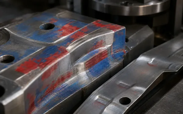
Red and blue spotting paste applied to a die surface reveals uneven contact patterns — bright transfer areas indicate high pressure zones, while untouched areas show insufficient contact that needs correction.
Red or blue spotting paste is applied to the sheet metal or the die surface. When the die closes, the paste transfers and reveals high-contact and low-contact areas — spots where pressure is concentrated and spots where the surface is not making proper contact.
This step is especially critical for draw and form operations where surface contact directly controls material flow and part shape.
Correction Loop Execution
This is the core of tryout.
Based on inspection data and spotting results, the toolmaker makes corrections to the die.
Common corrections include:
- Grinding forming surfaces to adjust material flow or reduce springback in specific areas
- Adding shims under inserts or pressure pads to change local pressure distribution
- Welding and re-machining to add material where the die surface has been cut too deep
- Adjusting cutting clearances by re-grinding punch or die sections
- Modifying draw beads or stretchers to control metal flow into deep-draw areas
After each correction, the die is re-stamped and the new parts are inspected.
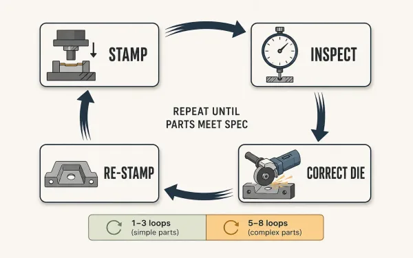
The core tryout correction loop cycles through four stages — stamp a part, inspect it against specification, correct the die, then stamp again — repeating until all dimensional and quality criteria are met.
This loop repeats — stamp, inspect, correct, stamp again — until the parts meet specification consistently.
For complex geometries, five to eight loops are typical. For simple parts, one to three may be enough.
The critical skill in this phase is knowing what to correct.
A dimensional deviation might be caused by springback (a material behavior), insufficient forming pressure (a process setting), or an incorrect die surface (a tooling error).
Each cause requires a different correction.
Misdiagnosing the root cause wastes loops and adds cost.
Final Validation and Approval
Once the die produces parts that meet all defined manufacturing quality requirements over a specified number of consecutive runs — typically 5 to 30 parts depending on project requirements — the tryout moves to final validation.
Samples go through a documented quality control and inspection process before they are submitted to the customer for approval.
Some projects require a formal PPAP (Production Part Approval Process) or equivalent sign-off.
What Gets Checked — and How
Tryout inspection is not a single pass — it is a layered process that catches different types of defects at different stages.
Forming Quality
Forming defects are the most visible and the most consequential.
Wrinkling indicates insufficient blank holder pressure or poor material flow control.
Thinning — measured by ultrasonic thickness gauges or sectioning — shows where the material has been stretched beyond its forming limit.
Cracking, the most severe failure, means the material has exceeded its elongation capacity in a specific area.
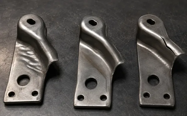
Three stamped parts from the same tryout run displaying common forming defects: (left) surface wrinkling from insufficient blank holder pressure, (center) thinning marks visible under raking light, (right) edge cracking at a tight-radius flange where material exceeded its elongation limit.
These defects often appear in combination.
A part might wrinkle in one area and crack in another, which points to a material flow imbalance rather than a simple pressure adjustment.
Dimensional Accuracy
CMM inspection measures the part against the CAD model at defined control points — hole positions, surface profiles, flange angles, and assembly reference features.
3D scanning provides a full-surface comparison, useful for identifying warpage or twist that point measurements might miss.
Checking fixtures offer a faster, production-oriented way to verify key features against go/no-go criteria.
Trim and Pierce Quality
Cut edge quality is evaluated by burr height, edge rollover, and shear band percentage.
Excessive burr usually indicates worn cutting clearances or misaligned punch-to-die alignment.
In progressive die metal stamping, trim and pierce stations are among the first to show wear, so their condition during tryout sets the baseline for tool life expectations.
Springback Behavior
Springback — the tendency of formed parts to spring back toward their original shape after the forming load is removed — is the most persistent challenge in die tryout.
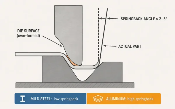
Cross-section view illustrating springback behavior: the dashed line shows the intended die shape, the solid outline shows the actual part after springback, and the orange zone indicates the over-form compensation built into the die surface to counteract material elastic recovery.
It is material-dependent, geometry-dependent, and process-dependent.
Aluminum alloys spring back more than mild steel. Tight-radius bends spring back more than gradual curves.
The toolmaker compensates by over-forming the die surface, but the exact amount requires iterative testing during tryout.
How Material and Thickness Change the Tryout Equation
Not all materials behave the same during tryout, and this directly affects how long the process takes and how many correction loops are needed.
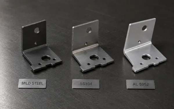
Three bracket parts stamped from the same die using different materials. Left: mild steel with minimal springback and close conformance. Center: stainless steel 304 with slight work-hardening marks. Right: aluminum 5052 with noticeable flange angle deviation due to higher springback.
Aluminum alloys (such as 5052-H32 or 6061-T6) have higher springback than carbon steel, which means the die surface needs more aggressive over-forming compensation.
Each correction loop may require smaller, more precise adjustments because the relationship between die geometry and part geometry is less predictable.
Stainless steel 304 work-hardens during forming, which means the forming surfaces must be tuned more carefully — over-correction in one area can create cracking in adjacent zones.
Sheet thickness matters as well.
Thin sheets (below 1.0 mm) are less forgiving of dimensional errors in the die because the material has less stiffness to resist minor variations in forming pressure.
Thick sheets (above 3.0 mm) require higher tonnage, which amplifies the effect of any misalignment in the die or press.
Material batch variation is another factor that is rarely discussed but practically significant.
Even within the same alloy specification, different coils can have slightly different yield strength and elongation properties.
A die that is validated on one material batch may need minor adjustments when the production material comes from a different supplier or heat number.
Experienced toolmakers account for this by running tryout with material from the same batch intended for production.
Prototype Die Tryout vs Production Die Tryout
Prototype and production tooling serve different purposes, and their tryout processes have different targets, different tolerances, and different risk profiles.
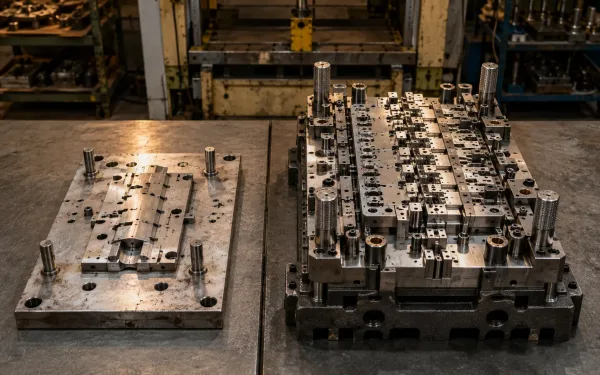
Left: a prototype die made from softer tool steel with simplified geometry, designed for part design validation with wider tolerances. Right: a production die built from hardened D2 tool steel with precision-ground forming surfaces, designed for hundreds of thousands of parts at tight tolerances.
A prototype die is built to validate part design and fit — not to prove long-term production capability.
Prototype tryout tolerances are typically 1.5 to 2 times wider than production tolerances.
The number of correction loops is lower (one to three), and the focus is on form and function rather than process stability.
The die may use softer tooling materials or simplified geometry to reduce lead time and cost.
A production die is built for volume.
Its tryout must prove that the die can produce hundreds of thousands of parts without dimensional drift, surface degradation, or unplanned downtime.
Production tryout requires tighter tolerances, more correction loops, and a formal validation protocol.
The die tooling is typically made from hardened tool steel (such as D2 or DC53), and the tryout must verify that cutting edges and forming surfaces maintain quality over extended runs.
The confusion between these two is a common source of problems.
A buyer who expects production-level consistency from a prototype die will be disappointed.
A buyer who accepts prototype-level validation for a production die is accepting risk that will surface during mass production.
When Is Tryout “Done” — Acceptance Criteria
Tryout is complete when the die produces parts that meet all of the following conditions:
- Dimensional conformance: All critical dimensions are within tolerance on a defined number of consecutive parts (typically 5 to 30, depending on project requirements).
- Surface quality: No visible defects (cracks, deep scratches, severe wrinkling, excessive burr) on production-intent surfaces.
- Repeatability: Part-to-part variation is within an acceptable range — usually specified as a percentage of the total tolerance band.
- Process stability: The die runs at target production speed without abnormal tonnage spikes, strip feeding issues, or part transfer failures.
- Tooling condition: After the validation run, the die shows no signs of abnormal wear, galling, or damage.
If the die meets these conditions, the toolmaker documents the tryout results, records the final press settings, and submits samples for customer approval.
If it does not meet them, the correction loop continues.
Key Takeaways
Die tryout is not a formality at the end of the tooling timeline — it is the phase where the die, the process, and the part are validated together under real production conditions.
The number and quality of correction loops during tryout directly determine how smoothly the die transitions into mass production.
Material choice, sheet thickness, and the distinction between prototype and production tooling all affect how long tryout takes and what “done” actually means.
For buyers, the most important question to ask a toolmaker is not “how fast can you finish tryout?” but “how do you run your correction loops, and what criteria do you use to decide the die is ready?”