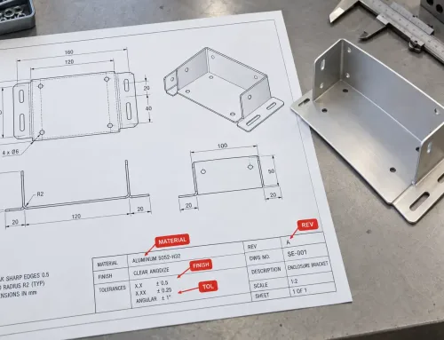
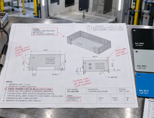
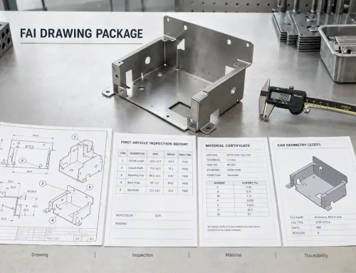
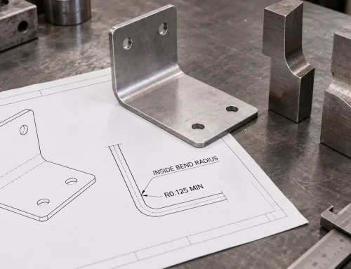
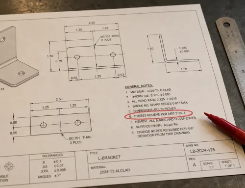
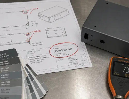
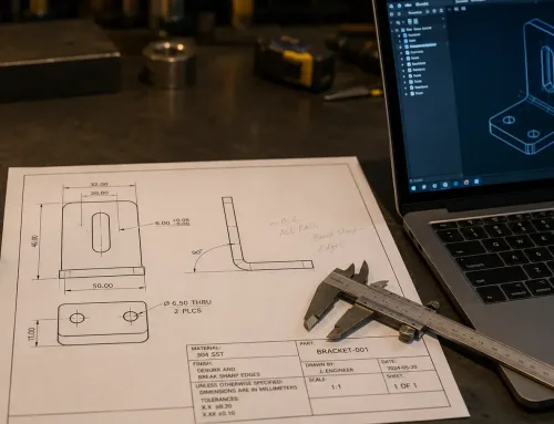
You have designed a sheet metal enclosure with a brushed stainless steel front panel. The prototype looks perfect. Then the first production batch arrives — and every panel has faint scratches across the visible surface. The parts are technically within tolerance, but they are not acceptable. When you ask the fabricator what went wrong, the response is: “The drawing didn’t say those surfaces needed protection.”
This scenario plays out more often than most engineers expect. The root cause is rarely negligence on the shop floor. It is a drawing that does not clearly define which surfaces are scratch-critical, the measurable sheet metal surface requirements, or how the fabricator should handle and package the parts to prevent damage. This article explains how to specify no-scratch areas on sheet metal drawings so that your parts arrive in the condition you intended.
When Does a Sheet Metal Part Need a No-Scratch Callout?
Not every surface on every part requires scratch protection. Adding no-scratch callouts to an entire drawing increases cost and lead time without adding value. The key is to identify surfaces where scratches cause functional or aesthetic failure.
Aesthetic surfaces are the most obvious candidates. Enclosure panels, visible covers, display bezels, and any surface that faces the end user falls into this category. A scratch on a hidden internal bracket is an inconvenience; a scratch on a brushed aluminum front panel is a rejected shipment.
Functional surfaces also warrant protection. Sealing faces — where gaskets or O-rings contact the sheet metal — can lose their sealing capability if scratched. Mating surfaces that slide against other components may wear prematurely if the surface finish is damaged. In these cases, the concern is not appearance but performance.
Post-processing surfaces represent a third category. If a part will be anodized, powder coated, or electroplated after fabrication, scratches in the base metal can telegraph through the finish. A shallow scratch that is invisible on raw steel may become a visible defect after powder coating. Specifying no-scratch zones before surface treatment prevents this problem.
Why “Do Not Scratch” Alone Fails as a Drawing Callout
A note that simply says “DO NOT SCRATCH” on a drawing is better than nothing, but it creates more problems than it solves. The phrase is vague, unenforceable, and leaves critical decisions to the fabricator’s interpretation.
Without a defined zone, the manufacturer does not know which surfaces to protect. Should they protect the entire part? Only the top surface? Only one face? When the zone is undefined, fabricators typically protect everything — which adds handling time and cost — or protect nothing, assuming the note is a general reminder rather than a requirement.
Without an acceptance criterion, there is no way to inspect the part. What counts as a scratch? A mark visible at arm’s length under shop lighting? A mark visible under magnification? A mark you can feel with a fingernail? The lack of a defined standard means the buyer and the fabricator may disagree on what is acceptable, leading to disputes after delivery.
Without handling and packaging instructions, even a perfectly manufactured part can arrive scratched. Sheet metal parts are vulnerable during transit — stacked parts abrade each other, loose parts shift against unpadded container walls, and protective films may not be applied if the drawing does not specify them. The callout must extend beyond the shop floor to the shipping dock.
Four Elements Every No-Scratch Callout Should Include
An effective no-scratch callout is not a single line of text. It is a set of four interlocking elements that tell the fabricator exactly what to protect, to what standard, how to verify, and how to ship. Missing any one element increases the risk of failure.
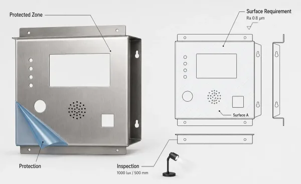
The four requirements needed to define, inspect and protect a no-scratch sheet metal surface.
Element 1 — Protected Zone
The first element identifies which surfaces require protection. On the drawing, this means calling out specific faces using leader lines, section views, or shaded zones with boundary marks. The callout should reference the exact view and surface — for example, “SURFACE A (SEE VIEW C-C)” — so there is no ambiguity about which face is protected.
For parts with multiple protected surfaces, a surface identification chart (sometimes called a surface lettering system) is the clearest approach. Each critical surface is assigned a letter (A, B, C) in the detail view, and a table in the drawing’s notes block defines the requirement for each lettered surface.
Element 2 — Surface Condition Requirement
The second element defines what “scratch-free” means in measurable terms. There are three common approaches:
- Surface roughness Ra specification: Use a surface roughness callout (e.g., Ra 0.8 μm max) if the surface already has a roughness requirement. This gives the fabricator a measurable threshold. Ra (roughness average) is the most common surface texture parameter in manufacturing.
- Visual standard reference: Reference an industry standard or a company-specific visual inspection standard (e.g., “VISUAL CLASS A PER [COMPANY] STD-001”). This is common for cosmetic surfaces where Ra alone does not capture the requirement.
- Limit sample: Provide or reference a physical limit sample that defines the maximum acceptable scratch severity. This is the most precise method but requires maintaining and shipping physical samples.
Element 3 — Inspection Method
The third element tells the fabricator how to verify compliance. Without a defined inspection method, the acceptance criterion is theoretical — everyone agrees on the rule, but nobody agrees on how to check it.
For visual standards, specify the lighting conditions (e.g., “inspect under 1000 lux fluorescent lighting at 500 mm viewing distance”), the viewing angle, and whether magnification is permitted. For Ra-based requirements, specify the measurement instrument (stylus profilometer or optical profilometer), the measurement direction, and the number of measurements per surface.
Element 4 — Handling and Packaging Instructions
The fourth element addresses how to protect the part after fabrication. This includes:
- Protective film: Specify whether a peel-off protective film (also called masking film) should be applied to the no-scratch surfaces. Include the film type if adhesion residue is a concern (e.g., low-tack PE film for stainless steel).
- Interleaving: For stacked parts, specify interleaving material (foam sheets, paper, or plastic dividers) to prevent sheet-to-sheet contact.
- Dedicated fixtures or packaging: For high-value or highly sensitive parts, specify custom packaging or cradles that prevent movement during transit.
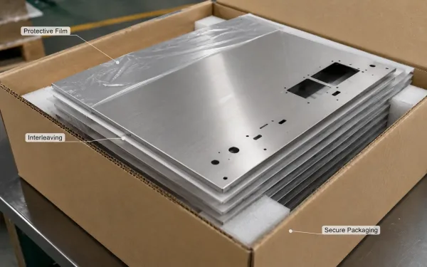
Protective film, interleaving sheets and secure packaging used to prevent scratches on finished sheet metal parts.
These instructions belong on the drawing — not in a separate email — because the drawing is the single source of truth that travels with the order from quotation through inspection.
How to Mark No-Scratch Zones on a Sheet Metal Drawing
With the four elements defined, the next question is where and how to place them on the drawing. The goal is to make the callout visible, unambiguous, and traceable to the specific surface.
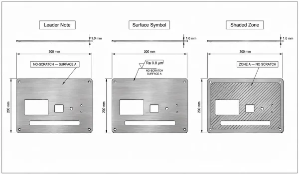
Comparison of leader notes, surface texture callouts and shaded zones for no-scratch requirements.
Method 1 — Leader Line with Custom Note
The simplest approach is a leader line (also called a balloon callout) pointing to the protected surface, with a text note that summarizes the requirement. A typical format:
NO-SCRATCH ZONE — SURFACE A Ra 0.8 μm MAX / VISUAL CLASS A APPLY PROTECTIVE FILM BEFORE SHIPPING
This method works well for parts with one or two protected surfaces. For parts with many protected surfaces, it becomes cluttered.
Method 2 — Surface Texture Symbol with Supplementary Requirement
If the surface already has a roughness callout under ISO 1302 or ASME Y14.36, the no-scratch requirement can be added as a supplementary requirement in the symbol’s extension. This keeps the callout within the standard annotation framework and avoids creating a separate custom note.
However, this method only works when the requirement can be expressed as a roughness value. For visual or tactile standards, a custom note is still necessary.
Method 3 — Shaded Zone with Boundary Callout
For large protected areas — such as an entire visible face of an enclosure panel — a shaded or hatched zone on the drawing view, with boundary lines and a zone identifier, provides the clearest visual indication. The zone identifier (e.g., “ZONE A — NO SCRATCH”) is then defined in the notes block.
Where to Place the Callout
Choose the drawing view that shows the protected surface most clearly. If the surface is not visible in the primary view, add a detail view or a section view specifically to show the no-scratch zone. Do not rely on the fabricator to infer which surface is protected from a partially visible edge in the main view.
For parts with multiple protected surfaces, a surface identification chart in the notes block — listing each surface letter, its location, and its specific requirement — is the most scalable approach.
Sheet Metal–Specific Risks That Make No-Scratch Callouts Critical
Sheet metal fabrication involves processes that create scratch risks at nearly every stage. Understanding these risks helps engineers decide which surfaces to protect and how strictly.
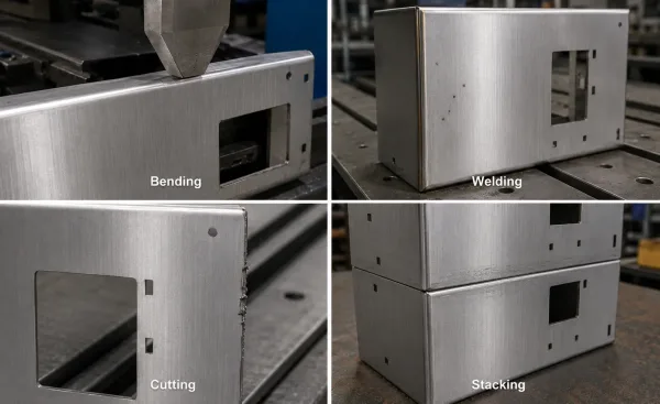
Scratch risks caused by bending, welding, cutting and stacking during sheet metal fabrication.
Bending and Forming
During bending, the sheet metal slides across the punch and die. On press brakes with worn tooling, or when the part is not properly supported, the sheet can drag across the die shoulder, leaving tooling marks on the surface. This is especially visible on brushed or polished finishes, where even a shallow mark disrupts the grain pattern.
Welding and Grinding
Welding spatter — small droplets of molten metal ejected during the arc welding process — can land on adjacent surfaces and bond to the base metal. Removing spatter often requires grinding or scraping, which leaves marks.
For no-scratch zones near weld joints, specifying a spatter-resistant coating or a physical shield during welding is more effective than trying to remove spatter after the fact.
Laser Cutting and Punching
Laser cutting produces dross (resolidified metal) on the bottom edge of the cut. Punching can leave burrs on the exit side. Both can scratch adjacent surfaces when parts are stacked or handled. Specifying sheet metal deburring requirements alongside no-scratch callouts prevents this.
Stacking and Handling
The most common source of scratches on finished sheet metal parts is not any single fabrication process — it is the way parts are handled and stored between processes.
Sheet metal parts are thin, flat, and often stacked directly on top of each other. Without interleaving material or protective film, the weight of the stack causes sheet-to-sheet abrasion. This is the easiest risk to prevent and the most commonly overlooked.
What Happens After You Submit the Drawing: How Fabricators Handle No-Scratch Requirements
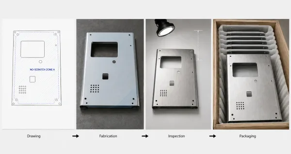
Workflow showing how a no-scratch drawing requirement is carried through fabrication, inspection and packaging.
Understanding the fabricator’s perspective helps engineers write callouts that are practical, cost-effective, and easy to follow.
When a fabricator receives a drawing with a no-scratch callout, the first step is interpretation. If the callout is clear — defined zone, measurable standard, inspection method — the fabricator can plan the production workflow accordingly.
If the callout is vague (“do not scratch, no marks”), the fabricator has two choices: ask for clarification (which adds days to the quotation cycle) or assume the strictest interpretation (which increases the quoted price).
No-scratch requirements affect cost and lead time. Protective film application, interleaving, dedicated packaging, and pre-shipment inspection steps all add time and material cost. The impact varies by part complexity and batch size. For a simple flat bracket in a batch of 1,000, the added cost is minimal. For a complex formed enclosure in a batch of 10, the added handling may represent a significant percentage of the unit price.
Prototype and production stages require different strategies. In prototype runs, parts are often hand-filed, hand-deburred, and individually wrapped — the protection is built into the low-volume workflow. In production runs, parts move through automated or semi-automated processes where handling is less controlled. The drawing should specify protection requirements that work at production volume, not just at prototype volume.
Common Mistakes Engineers Make with No-Scratch Callouts
Even with good intent, engineers often make callout errors that create problems for the fabricator or increase cost unnecessarily.
Calling out the entire drawing instead of specific zones is the most frequent mistake. A blanket “ALL SURFACES — NO SCRATCH” note forces the fabricator to treat every surface as critical, which increases handling time and cost. Most parts have only two or three truly critical surfaces. Identifying them specifically is more effective and less expensive.
Specifying Ra values that are tighter than necessary is another common error. If the base material is cold-rolled steel with a standard Ra of 1.6 μm, specifying Ra 0.4 μm on a cosmetic surface requires additional sheet metal finishing operations such as polishing or buffing, which add significant cost. Match the requirement to the function: a sealing face may need Ra 0.8 μm, but a surface that only needs to look clean under normal lighting may be fine at Ra 1.6 μm.
Forgetting to update callouts after design changes creates problems when the protected surface moves, changes size, or changes function. If the drawing is revised to add a new weld joint adjacent to a no-scratch zone, the zone boundaries may need to expand to account for weld spatter risk. Drawing revision discipline applies to surface callouts the same way it applies to dimensions and tolerances.
Omitting packaging instructions is the final common mistake. A perfectly manufactured part that arrives scratched because it was shipped loose in a cardboard box has failed just as completely as a part that was scratched on the shop floor.
The drawing should specify protective film, interleaving, or custom packaging as part of the no-scratch requirement — not as an afterthought.
Pre-Submission Checklist for No-Scratch Requirements
Before submitting a drawing with no-scratch callouts, verify each of the following:
- Each protected surface is identified with a unique letter or zone ID in the drawing view
- The surface condition is specified as a measurable value (Ra), a visual standard, or a limit sample reference
- The inspection method is defined (lighting, viewing distance, instrument type)
- Handling instructions are included (protective film type, interleaving material)
- Packaging instructions are specified for shipping
- The callout references the correct drawing view (the protected surface is clearly visible)
- The requirements are realistic for the material and fabrication process
- The callout has been reviewed against the latest drawing revision
FAQs
Need a manufacturing partner who understands surface protection requirements? SR-MFG’s engineering team reviews drawings for no-scratch callouts and provides DFM feedback before quotation. Contact us to discuss your project.