You have a aluminum enclosure design on your desk — maybe it’s a control box, a sensor housing, or an instrument case. The sheet metal is cut and bent, and now you need to join the seams. TIG welding is the safe choice your team already knows. Laser welding promises less distortion and faster cycles. Which one actually fits your part?
The answer depends on sheet thickness, alloy type, joint geometry, appearance requirements, and production volume. There is no universal winner. But there is a clear decision framework, and that is what this article provides.
Why Aluminum Enclosures Demand a Different Welding Approach
Aluminum behaves differently from steel under a welding arc or a laser beam. Its thermal conductivity is roughly four times that of carbon steel, which means heat spreads away from the weld zone almost instantly. In thin-sheet enclosures, this rapid heat dissipation causes two problems: distortion of adjacent panels and inconsistent weld penetration along long seams.
Then there is the oxide layer. Aluminum naturally forms a thin film of aluminum oxide (Al₂O₃) on its surface. This oxide melts at around 2,072 °C — more than three times the melting point of the base aluminum at 660 °C. If the oxide is not disrupted before or during welding, it creates inclusions and porosity in the joint. TIG welding handles this with alternating current (AC), which performs a cleaning action on each half-cycle. Laser welding relies on the sheer energy density of the beam to vaporize the oxide.
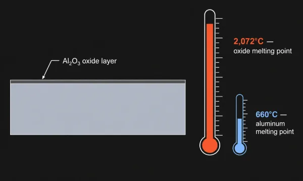
A cross-section technical illustration showing the aluminum oxide (Al₂O₃) layer on the aluminum base metal, with labeled melting point values indicating the challenge this creates during welding.
Enclosures add another layer of complexity. A typical aluminum housing has thin walls (often 1.0–2.0 mm), multiple intersecting seams, and tight dimensional tolerances. The weld must be strong enough to hold the assembly together, smooth enough for post-processing (anodizing, powder coating), and in many cases, leak-tight for IP-rated protection. These requirements push the welding process selection beyond generic comparisons.
How Laser Welding and TIG Welding Work — A Quick Comparison
In sheet metal welding, TIG (Tungsten Inert Gas, also called GTAW) uses an electric arc between a non-consumable tungsten electrode and the workpiece. The arc melts the base metal and, when needed, a manually fed filler wire. An inert shielding gas — typically pure argon for aluminum — protects the molten pool from atmospheric contamination. TIG is prized for its precise heat control and clean weld bead appearance.
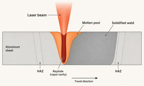
Laser welding (Laser Beam Welding, or LBW) uses a focused beam of high-intensity coherent light, usually from a fiber laser source. When the beam hits the metal surface, it creates a small cavity called a keyhole — a column of vaporized metal surrounded by molten aluminum. As the laser travels along the joint, the molten pool behind the keyhole solidifies into a narrow, deep weld.
A cross-section view showing how a focused laser beam creates a keyhole cavity in aluminum, with the molten pool and solidified weld zone labeled.
The fundamental difference: TIG delivers heat broadly through an electric arc, while laser concentrates energy into a spot smaller than 1 mm in diameter. This distinction drives everything that follows — speed, distortion, joint requirements, and cost.
Key Differences That Matter for Aluminum Enclosures
Heat Input and Distortion Control
Laser welding achieves a power density exceeding 1 MW/cm², roughly 200 times higher than TIG per square millimeter. Because the energy is delivered so rapidly and concentrated within a narrow zone, heat does not have time to spread into the surrounding material.
The result: a heat-affected zone (HAZ) of just 1–2 mm on either side of the weld, and distortion typically below 0.1 mm over a 1-meter length.
TIG welding operates at a much lower power density. The arc is broader, travel speed is slower, and heat accumulates in the workpiece. For thin aluminum sheet (under 2 mm), TIG-induced distortion can reach 2–3 mm over the same length — enough to cause visible panel warping, misaligned screw holes, or gaps in gasket channels.
For enclosures where dimensional accuracy matters — mounting flanges, PCB standoffs, sealing surfaces — this difference in distortion is often the deciding factor.
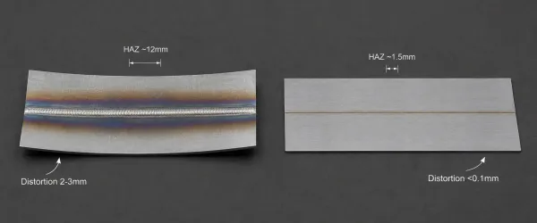
A top-down comparison showing the visible heat-affected zone (discoloration) around TIG welds versus laser welds on identical aluminum panels, highlighting the distortion difference.
Welding Speed and Production Throughput
Laser welding is typically 3–4 times faster than TIG on aluminum sheet. A continuous laser weld on 1.5 mm 5052 aluminum can travel at 2.0–2.5 m/min. TIG welding on the same material usually runs at 0.5–0.8 m/min.
Speed matters beyond cycle time. Faster welding means less total heat input per part, which further reduces distortion. It also means fewer fixtures are needed to hold panels flat during welding — a significant cost factor in enclosure production.
The table below summarizes typical speed ranges for enclosure-scale aluminum welding:
| Welding Method | Typical Travel Speed (1–2 mm Al) | Relative Cycle Time |
|---|---|---|
| Laser welding | 2.0–2.5 m/min | 1× (baseline) |
| TIG welding | 0.5–0.8 m/min | 3–4× longer |
Material Thickness Range
Aluminum sheet thickness is the single most practical factor in choosing between TIG and laser welding.
- Below 2 mm: Laser welding excels. The concentrated beam penetrates thin material quickly without burn-through. Many thin-wall enclosure seams can be welded autogenously — without filler wire — reducing post-weld grinding.
- 2–3 mm: Both processes are viable. Laser still has the speed advantage, but TIG with filler wire can provide better gap bridging if the joint fit-up is imperfect.
- Above 3 mm: TIG welding becomes the more reliable choice. Laser penetration drops off, and multiple passes may be needed. TIG with ER4043 or ER5356 filler wire delivers consistent full-penetration welds at this range.
Most aluminum enclosures fall in the 1.0–2.5 mm range, which puts them squarely in laser territory for production work and in the “either works” zone for prototypes or small batches.
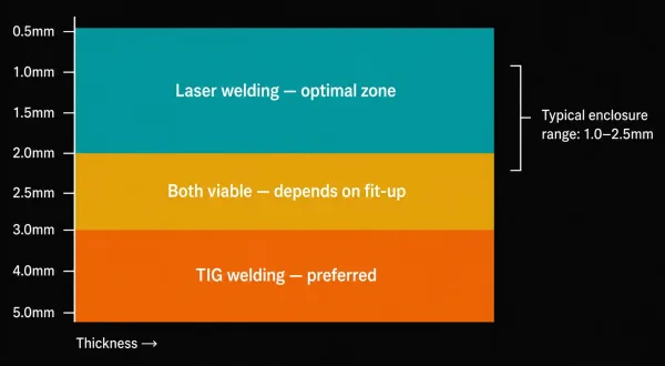
A visual guide mapping aluminum sheet thickness ranges to the recommended welding process, showing where laser welding, TIG welding, or both are suitable.
Weld Appearance and Post-Processing
Enclosures often require a finished surface — anodized, powder-coated, or brushed. The weld quality directly affects the final appearance.
Laser welds are smooth, narrow (typically 1–2 mm wide), and virtually spatter-free. Porosity is extremely low, often below 0.1%. For aluminum anodizing, this means minimal surface preparation and more consistent color uptake across the weld zone.
TIG welds are wider (3–6 mm) and may exhibit slight porosity in the range of 1–3%. TIG produces a recognizable “stack of dimes” bead profile that, while aesthetically acceptable on some products, often requires grinding before finishing. On thin sheet, grinding can weaken the joint or create uneven surfaces.
For enclosures with strict cosmetic requirements — consumer electronics housings, medical device cases, display kiosks — laser welding significantly reduces post-processing time and cost.
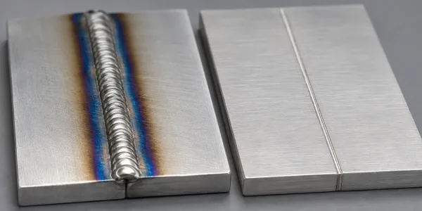
A macro close-up comparison showing the visual difference between a TIG weld bead (wider, textured) and a laser weld bead (narrow, smooth) on aluminum surface.
Joint Fit-Up and Gap Tolerance
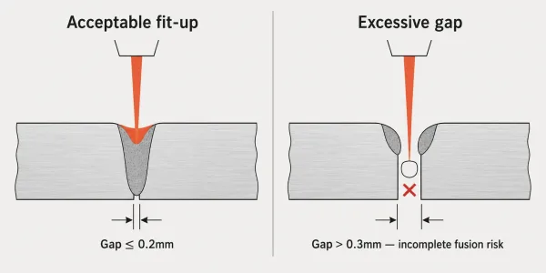
Laser welding is less forgiving of poor fit-up. The beam is narrow, and gaps exceeding 0.1–0.2 mm can result in incomplete fusion or undercut. This means the sheet metal must be cut and bent to tight tolerances before welding. Wobble laser heads (which oscillate the beam) can accommodate some variation, but they are not a substitute for accurate fabrication.
TIG welding handles gaps more gracefully. The manual addition of filler metal lets the operator bridge openings, compensate for minor misalignment, and build up reinforcement as needed. If your enclosure design has complex three-dimensional joints or if your custom sheet metal fabrication supplier cannot hold tight bend tolerances, TIG provides a safety margin.
A technical cross-section showing the difference between an acceptable joint gap (within laser tolerance) and an excessive gap that would cause welding defects.
Shielding Gas and Operating Cost
For aluminum welding, both processes use pure argon as shielding gas. However, the consumption rates differ. TIG welding typically requires 12–18 L/min of argon flow. Laser welding uses lower flow rates (8–15 L/min) but may need additional gas for back-purging on critical seams.
In production runs, shielding gas cost is a minor factor compared to labor and cycle time. But in high-volume operations, the cumulative savings from lower gas consumption and faster throughput can be meaningful.
Which Process for Which Aluminum Enclosure?
Rather than making a blanket recommendation, the table below provides a decision matrix based on typical enclosure parameters:
| Enclosure Characteristic | Recommended Process | Reason |
|---|---|---|
| Wall thickness < 2 mm, long straight seams | Laser | Speed, minimal distortion, no filler needed |
| Wall thickness > 3 mm, structural loads | TIG | Better penetration, proven reliability |
| High cosmetic requirements (anodized/coated) | Laser | Smooth bead, low porosity, less post-processing |
| Complex 3D joints, mixed thicknesses | TIG | Flexibility, gap tolerance |
| Prototype or small batch (< 50 units) | TIG | Lower setup cost, no fixture investment |
| Production volume > 500 units | Laser | Cycle time savings offset setup cost |
| 5052-H32 alloy (enclosure standard) | Laser or TIG | Both work well; laser faster on thin stock |
| 6061-T6 alloy (structural enclosures) | TIG preferred | Heat cracking risk with laser; filler helps |
If your enclosure falls into multiple categories — for example, thin walls but high cosmetic requirements — the cosmetic and distortion priorities usually outweigh thickness considerations, and laser welding is the stronger choice.
Common Pitfalls When Welding Aluminum Enclosures
Even with the right process selected, execution errors can ruin an enclosure run. Here are the most frequent issues we see in production:
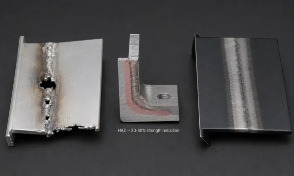
A composite image showing three common welding defects encountered during aluminum enclosure production: burn-through on thin walls, HAZ softening zones, and surface discoloration affecting anodizing quality.
Underestimating heat-affected zone (HAZ) softening on 6061-T6 aluminum. The T6 temper gives 6061 its strength, but welding destroys the heat treatment in the HAZ. Tensile strength in the HAZ can drop by 30–40%. If the enclosure carries structural loads (rack-mounted equipment, outdoor housings), the weld joint must be designed with this strength reduction in mind — not the base metal specification.
TIG current set too high on thin walls. A common mistake when welding 1.0–1.5 mm aluminum: the operator uses the same amperage as thicker material, causing edge melting and burn-through. Thin-wall TIG requires lower amperage (60–90 A), faster travel speed, and often a smaller diameter tungsten (1.6 mm).
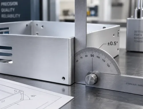
Laser welding without confirming bend accuracy. Laser demands tight joint fit-up. If the enclosure’s bend angles are off by even 1–2 degrees, the seam gap at the corner can exceed the laser’s tolerance. Before committing to laser welding, verify that your sheet metal supplier can hold bend tolerances within ±0.5 degrees.
Skipping weld cleaning before anodizing. Both TIG and laser welds produce oxide discoloration adjacent to the bead. If this oxide is not removed before anodizing, the weld zone absorbs dye differently from the base material, creating visible color bands. Chemical cleaning or light mechanical polishing before the anodizing bath eliminates this issue.
FAQs
Looking for a manufacturing partner to produce your aluminum enclosures? SR-MFG provides sheet metal fabrication, precision welding (TIG and laser), and full finishing services — from prototype to production volume. Request a quote or send your drawings to