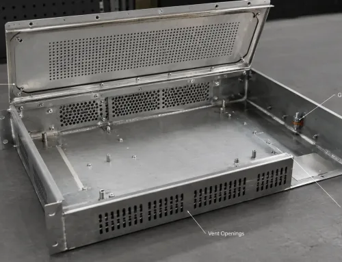
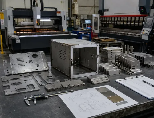
You have designed a sheet metal enclosure. The walls are 1.2 mm thick. You need M4 screws to hold a cover plate that will be removed for maintenance fifty times over the product’s life. Direct tapping won’t work — there isn’t enough material for reliable threads. So what do you specify?
This is one of the most common design decisions in sheet metal fabrication, and one of the easiest to get wrong. The wrong choice leads to stripped threads at assembly, rejected quotes at the RFQ stage, or fasteners that loosen after a year in the field. The right choice depends on panel thickness, load requirements, assembly cycle count, and how the part will be finished.
This guide explains why thin panels resist conventional tapping, compares six threading methods with their design parameters, and gives you a framework for specifying the right solution on your drawing.
Why Thin Panels Cannot Be Tapped Directly
The standard rule for a strong tapped thread is that the engagement depth — the length of thread contact between the screw and the parent material — should equal at least one times the fastener’s diameter.
For M4 threads (4 mm diameter), that means 4 mm of engaged material. For M5, it means 5 mm.
Typical sheet metal thickness for these applications is 0.8 to 2.0 mm. At those thicknesses, an M4 tapped hole produces only one to two full thread turns. That is not enough to resist normal assembly torque, let alone repeated disassembly or vibration loads.
The effective thread count can be estimated with a simple formula:
Effective thread turns = panel thickness ÷ thread pitch
For example, M4 × 0.7 mm pitch in 1.4 mm panel:
1.4 ÷ 0.7 = 2.0 turns
That is borderline for light loads and inadequate for anything structural. Most engineers consider three turns a minimum for moderate loads and five or more for heavy-duty applications.
This is why thin sheet metal requires alternative threading methods. The goal is always the same: create enough thread engagement to handle the design load, regardless of how thin the panel is.
Six Methods for Adding Threads to Thin Sheet Metal
There are six practical approaches. Each solves the insufficient-material problem differently, and each has clear limits on when it works and when it doesn’t.
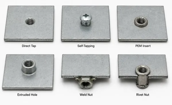
Comparison of direct tapping, self-tapping screws, self-clinching inserts, extruded holes, weld nuts and rivet nuts.
Direct Tapping
Direct tapping means cutting threads into a pre-drilled hole with a standard tap. It is the simplest method and requires no additional hardware. But it only works when the panel is thick enough for adequate engagement.
Minimum thickness: 2.0 mm for M3, 2.5 mm for M4, 3.0 mm for M5 (mild steel; aluminum requires slightly more due to lower shear strength).
Direct tapping is viable for medium-thick panels and structural applications where the threads will not be cycled frequently.
For panels under 2.0 mm, skip this method entirely.
Self-Tapping Screws
Self-tapping screws (also called thread-forming or sheet metal screws) cut their own threads as they are driven into a pilot hole.
No pre-tapping is needed. They install quickly and work well in thin gauge material — down to about 0.5 mm for small screw sizes.
The trade-off is limited reusability. Self-tapping threads in thin metal typically survive one to three assembly cycles before they strip.
They are best suited for light-duty, non-structural covers that are assembled once or rarely opened.
Self-Clinching Inserts (PEM-Style)
Self-clinching fasteners for sheet metal are the industry standard for adding permanent, reusable threads to thin panels.
A precision fastener — typically a nut, stud, or standoff — is pressed into a sized hole. The fastener’s knurled shank displaces the surrounding sheet material, causing it to cold-flow into an annular groove on the fastener body.
This creates a mechanical lock that resists both rotation and pull-out.
Self-clinching inserts work in panels as thin as 0.5 mm for M2.5 hardware.
Once installed, they provide full-strength internal threads rated for repeated assembly.
Common types include:
- Standard clinching nuts — for general-purpose panels
- Floating nuts — for assemblies with alignment tolerance stack-up
- Blind nuts — for closed housings where the back side is inaccessible
The key requirement is that the host sheet must be softer than the insert — typically at least 20–30 HV lower in hardness — so the sheet material can flow into the locking groove during installation.
Extruded Holes (Flow Drilling / Burring)
In this method, a rotating or pressed tool pushes through the sheet metal, forming a raised collar or bushing around the hole from the parent material itself.
The collar increases the local thickness, creating enough material depth to be tapped with standard threads.
Extruded holes require no additional hardware.
The thread is cut directly into the formed collar, which can be two to three times the original sheet thickness.
This makes the method clean, strong, and suitable for applications where protrusions on the back side are acceptable.
The limitation is that the extrusion height and post-form wall thickness depend on the original material’s ductility.
Hard or brittle materials may crack during forming.
Weld Nuts
A weld nut — typically a flanged nut with projection weld points — is placed over a hole and welded permanently to the sheet.
This creates the strongest possible connection, with no reliance on the parent material’s thread capacity.
Weld nuts are ideal for heavy-duty, high-vibration applications such as automotive chassis and industrial equipment.
They work well in thin panels because the weld provides all the structural strength.
The downsides are permanent attachment, heat distortion risk, and surface treatment constraints.
Welding must be done before powder coating or anodizing, and weld spatter may require post-weld cleaning.
Rivet Nuts (Nutserts)
Rivet nuts are tubular inserts that are placed into a hole and compressed with a pulling tool.
The body expands behind the panel, locking the insert in place.
They provide a reusable internal thread and can be installed from one side of the panel using a hand tool.
Rivet nuts are popular in field service, repair, and hollow-section applications where a bench press is not available.
They work in panels as thin as 0.8 mm for small sizes.
Compared to self-clinching inserts, rivet nuts have lower push-out and torque-out strength and leave a slight bulge on the back side.
But they require no special equipment, which makes them practical for low-volume or on-site work.
Choosing the Right Method — A Decision Framework by Panel Thickness
The six methods overlap in capability, but panel thickness narrows the field quickly.
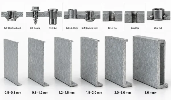
Recommended threading methods shown across different thin sheet metal thickness ranges.
The table below maps recommended methods to thickness ranges and load levels.
| Panel Thickness | Light Load (covers, brackets) | Moderate Load (serviceable panels) | Heavy Load (structural, vibration) |
|---|---|---|---|
| 0.5–0.8 mm | Self-clinching inserts | Self-clinching inserts | Self-clinching inserts (heavy-duty series) |
| 0.8–1.2 mm | Self-tapping screws | Self-clinching inserts, rivet nuts | Self-clinching inserts |
| 1.2–1.5 mm | Direct tapping (M3 only) | Extruded holes, self-clinching inserts | Self-clinching inserts, weld nuts |
| 1.5–2.0 mm | Direct tapping (M3–M4) | Direct tapping (M3), extruded holes (M4+) | Weld nuts, self-clinching inserts |
| 2.0–3.0 mm | Direct tapping | Direct tapping | Direct tapping, weld nuts |
| 3.0 mm+ | Direct tapping | Direct tapping | Direct tapping |
Material matters too.
Aluminum (5052, 6061) has lower shear strength than mild steel (SPCC, A36), so tapped threads in aluminum strip more easily.
For aluminum panels under 2.0 mm, self-clinching inserts or extruded holes are almost always a better choice than direct tapping.
Stainless steel (304, 316) is harder and more prone to galling — use lubrication if tapping, and verify that the insert material is compatible with the host sheet.
Design Parameters for Each Method
Specifying the right method is only half the job.
The other half is getting the design parameters correct on your drawing so the sheet metal fabricator can produce the feature without guesswork.
Self-Clinching Inserts
- Hole diameter: Per manufacturer catalog (typically the insert pilot diameter ± 0.05 mm). Oversized holes reduce retention strength; undersized holes cause material damage during press-in.
- Minimum hole-to-edge distance: At least two times the hole diameter. Closer than that, the sheet material can bulge outward during installation, reducing pull-out strength.
- Minimum hole-to-bend distance: At least three times the hole diameter plus the bend radius. Holes too close to a bend deform into an oval shape during press-in.
- Sheet hardness: The host sheet must be at least 20–30 HV softer than the insert material. A steel insert cannot be clinched into hardened steel sheet.
- Installation force: Typically 5–30 kN depending on insert size. This requires a controlled press — not a hammer.
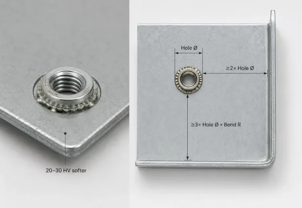
Self-clinching nut installation showing hole, edge and bend spacing requirements in thin sheet metal.
Extruded Holes
- Extrusion height: Typically two to three times the original sheet thickness. A 1.0 mm panel can form a 2.0–3.0 mm collar.
- Post-extrusion wall thickness: The collar wall thins during forming. Expect roughly 60–70% of the original sheet thickness at the collar.
- Minimum collar diameter: Should be at least 1.5 times the tap drill diameter to prevent cracking.
- Tap drill size: Standard metric tap drill chart applies to the extruded collar as if it were solid material of that thickness.
Weld Nuts
- Flange-to-edge distance: At least equal to the nut flange diameter. Projection welds need a flat contact area around the nut.
- Weld spot spacing: If multiple weld nuts are on the same panel, maintain at least 20 mm between them to prevent heat distortion overlap.
- Post-weld distortion zone: Expect a slight raised area (0.1–0.3 mm) around each weld point. Account for this in assemblies with tight flatness requirements.
How to Specify Threaded Features on Your Drawing
A common source of manufacturing delays is a drawing that calls out a thread size but not the method or hardware.
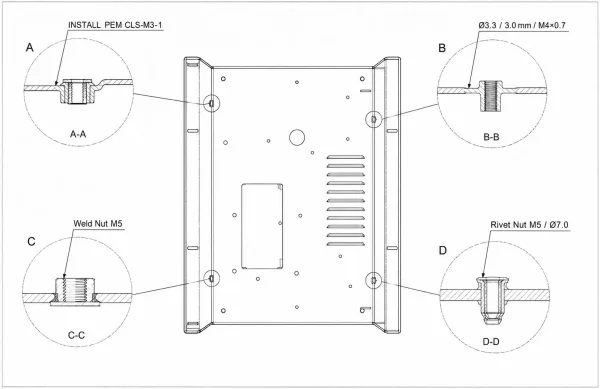
Drawing examples showing how to specify PEM inserts, extruded holes, weld nuts and rivet nuts.
The manufacturer cannot quote, plan, or produce the feature without knowing how you want it made.
PEM Insert Callout
Specify the exact manufacturer part number on the drawing.
The format is typically:
INSTALL PEM [Series]–[Thread Size]–[Shank Code]
Example:
“INSTALL PEM CLS-M3-1”
for a standard self-clinching nut, M3 thread, shank code 1 (for panels 0.8–1.0 mm thick).
If you are not using a specific PEM brand, write the insert type and full specification:
“Self-clinching nut, M4, for 1.5 mm panel, per [manufacturer catalog reference].”
Extruded Hole Callout
An extruded hole callout should include three pieces of information:
- Hole diameter (the tap drill size, e.g., Ø3.3 mm for M4)
- Extrusion height (e.g., 3.0 mm minimum)
- Thread specification (e.g., M4 × 0.7, 3 turns minimum)
Example note:
“Extrude Ø3.3 hole to 3.0 mm height, tap M4 × 0.7, min 3 full threads.”
Weld Nut Callout
Specify the nut type, size, and weld requirement:
“Weld nut M5, projection weld, per [standard or part number]. Post-weld torque test: 15 N·m minimum.”
Rivet Nut Callout
Include the rivet nut part number, hole size, and grip range:
“Rivet nut M5, body Ø7.0, grip range 0.5–2.5 mm, per [manufacturer part number].”
Pre-Submission Checklist
Before sending your drawing to a sheet metal shop, verify these items are on the drawing:
- Panel thickness is noted in the title block or general notes.
- Thread size and pitch are specified for every threaded hole.
- The threading method is specified (direct tap, PEM insert, extruded hole, weld nut, or rivet nut).
- For PEM inserts: the exact part number, series, and shank code are listed.
- Minimum edge distance and bend distance are verified against the insert catalog.
- Surface treatment is specified, and the installation sequence (before or after coating) is confirmed.
- Assembly cycle count is considered — specify inserts for serviceable panels, direct tap or weld for permanent joints.
Surface Treatment and Installation Sequencing
The order in which hardware is installed relative to sheet metal surface treatment is a frequent source of manufacturing errors.
Getting it wrong can destroy the insert, ruin the finish, or both.
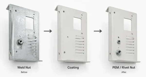
Installation sequence showing weld nuts before coating and self-clinching or rivet nuts after coating.
Self-clinching inserts must be installed after powder coating, anodizing, or chromate conversion.
Chemical baths used in these processes corrode steel inserts in aluminum panels. Plating baths can also deposit material in the threads, making the insert unusable.
Install inserts as the last fabrication step.
Weld nuts must be installed before coating.
Welding on a coated surface creates burn marks, spatter, and adhesion failures around the weld zone. The weld area also needs to be clean bare metal for a reliable joint.
Extruded holes can be formed before or after coating, but tapping after coating generally produces cleaner threads.
If the extrusion is done before coating, verify that the coating thickness does not reduce the thread fit.
Rivet nuts follow the same rule as self-clinching inserts — install after coating for the same corrosion and thread-fouling reasons.
| Method | Install Sequence | Reason |
|---|---|---|
| Self-clinching inserts | After coating | Chemical baths corrode inserts; plating fouls threads |
| Weld nuts | Before coating | Welding on coated surface causes defects |
| Extruded holes | Before or after coating | Post-coating tapping gives cleaner threads |
| Rivet nuts | After coating | Same as self-clinching inserts |
| Direct tapping | Before coating | Coating fills thread flanks, reducing fit |
If your part requires both weld nuts and self-clinching inserts — for example, a chassis with welded mounting points and PEM nuts for a removable cover — the weld nuts go in first (before coating), the part gets coated, and the PEM inserts go in last (after coating).