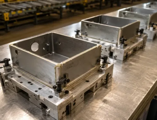
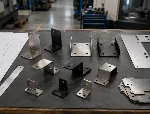
A robotic welding arm follows the same path every time. That much is true. But if you have ever received a batch of welded sheet metal assemblies where the door gaps vary by a millimeter, the mounting holes drift out of position, or the frame twists just enough to make final assembly difficult, you already know that path repeatability and assembly repeatability are not the same thing.
The robot repeats its programmed motion. It does not guarantee that the output parts will be identical. That guarantee comes from three layers that sit upstream of the welding arc: part design, fixturing, and process control. When any one of these layers is inconsistent, the finished assemblies will be too—no matter how precise the robot is.
This article explains what repeatability actually means in the context of robotic welding for sheet metal assemblies, what conditions must be met to achieve it, and how engineers and procurement teams can evaluate whether a supplier’s robotic welding capability will deliver the consistency their products require.
Why Robotic Welding Does Not Automatically Mean Repeatable Assemblies
The most common misconception about robotic welding is that the robot itself is the source of repeatability. In reality, the robot is the most consistent variable in the system. Industrial arc-welding robots typically maintain a path repeatability of ±0.05 to ±0.1 mm. That figure describes how closely the welding torch returns to the same programmed position across cycles.
But the torch position is only one part of the equation. If the sheet metal parts being loaded into the fixture vary in dimension—if a bent flange is 0.3 mm off, if a laser-cut blank has edge burrs that affect fit-up, if the incoming material thickness fluctuates within the tolerance band—the robot will faithfully weld each slightly different assembly with the same precision. The result is a set of parts that are all welded consistently to slightly different geometries.
Consider a welded electrical cabinet frame. The robot welds each corner joint to the same path and parameters. But if the side panels arrive with 0.5 mm variation in their bend angle, the frame assemblies will have inconsistent door gaps. The robot did its job. The variation came from upstream.
What Repeatability Means in Robotic Welding for Sheet Metal
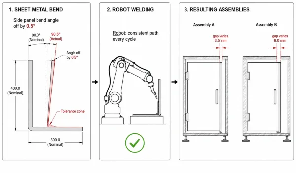
This diagram illustrates how dimensional variation in incoming sheet metal parts (e.g., bend angle deviation) is faithfully reproduced by the robot, resulting in inconsistent finished assemblies despite consistent weld paths.
When engineers and procurement teams discuss repeatability in robotic welding, two distinct concepts often get conflated:
Robot path repeatability is the mechanical precision of the robot arm—how closely it returns to the same programmed position. This is a specification of the robot hardware, typically ±0.05 mm for standard industrial welding robots. It is rarely the limiting factor.
Assembly repeatability is the consistency of the finished welded parts across a production run. This is what the buyer actually cares about: will every assembly in a batch of 500 fit into the same enclosure, mount to the same bracket, align with the same door? Assembly repeatability depends on the robot, the fixture, the incoming part quality, and the welding process parameters working together.
The gap between these two concepts is where most problems occur. A supplier may have a robot with excellent path repeatability, but if the fixture is worn, the incoming parts vary, or the weld sequence introduces uneven thermal distortion, the finished assemblies will not be consistent.
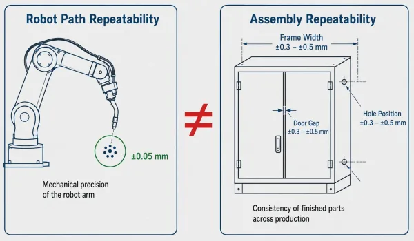
A side-by-side comparison showing that robot path repeatability (mechanical precision of the arm) and assembly repeatability (consistency of finished welded parts) are two different measurements with different tolerance ranges.
For sheet metal assemblies—where material thicknesses are typically 0.5 mm to 6 mm and tolerances on bend angles and hole positions are often ±0.2 to ±0.5 mm—the fit-up quality before welding has a direct and measurable impact on the final assembly dimensions.
Part Design Prerequisites for Repeatable Robotic Welding
Before a robot can weld an assembly repeatedly, the part design must allow it. Certain design choices make robotic welding straightforward; others introduce variability that is difficult to control, regardless of the automation investment.
Joint type and accessibility. Robotic welding works best with sheet metal lap joints, fillet joints, and T-joints that the welding torch can access from a consistent angle. Complex three-dimensional weld paths, joints in deep recesses, or welds that require the torch to reach around obstructions introduce programming complexity and reduce the consistency of weld placement. During design review, the question to ask is: can the torch reach every weld location from a stable position without repositioning the part?
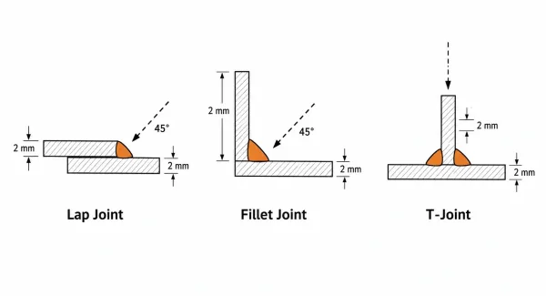
Three common joint types for robotic sheet metal welding — lap joint, fillet joint, and T-joint — shown in cross-section with welding torch approach angles indicated.
Fit-up tolerance. The gap between parts at the joint directly affects weld quality and consistency. For sheet metal assemblies, a gap of more than 0.5 mm at the joint can cause inconsistent penetration, porosity, or burn-through. Robotic welding is less forgiving of fit-up gaps than manual welding, because the operator cannot adapt the arc in real time the way a skilled welder can. Designing parts with tight fit-up tolerances—through accurate laser cutting, controlled bend angles, and proper nesting—is the first step toward repeatability.
Material thickness consistency. Variations in sheet thickness affect heat input requirements and weld penetration. If a batch of material ranges from 1.9 mm to 2.1 mm on a nominal 2 mm sheet, the welding parameters optimized for 2 mm may not produce consistent results across the full range. Specifying thickness tolerance on purchase orders—typically per ASTM A480 or EN 10051—helps control this variable.
Weld seam uniformity. Designs that use consistent weld lengths, similar joint geometries across the assembly, and symmetrical weld patterns are easier to fixture, program, and control. Asymmetric designs or assemblies with a mix of very short and very long welds on the same part can introduce uneven thermal distortion that is harder to predict and control.
Fixturing — The System Layer That Determines Assembly Repeatability
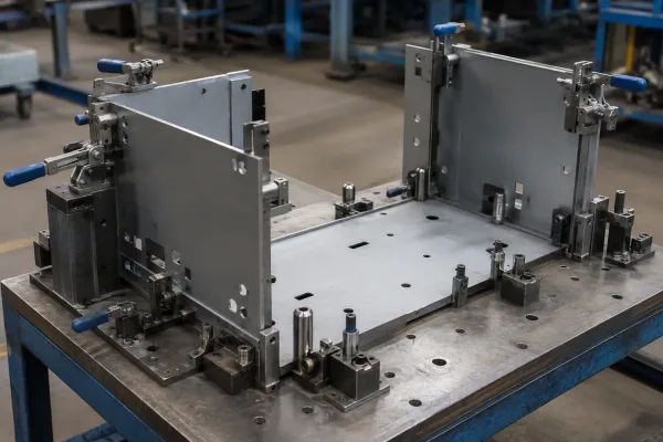
A dedicated welding fixture that positions and clamps sheet metal cabinet panels using locating pins and datum surfaces before robotic welding.
If part design sets the conditions for repeatability, the fixture enforces them. A welding fixture holds the sheet metal components in the correct relative position while the robot welds. Its precision, condition, and design directly determine whether the finished assembly will meet dimensional requirements.
Positional accuracy. A well-designed fixture locates each component using datum surfaces, pins, and clamps that constrain the parts in all relevant degrees of freedom. For a typical sheet metal cabinet, the fixture must control the position of each panel relative to the base within ±0.1 to ±0.2 mm to achieve consistent assembly dimensions after welding.
Clamping force and thin-wall deformation. Sheet metal parts are thin and flexible. Excessive clamping force can deform the part before welding; insufficient clamping allows the part to shift during the welding cycle. Finding the right balance—particularly for materials under 2 mm thick—requires fixture design experience and, often, iterative adjustment during the first-article run.
Fixture wear over time. Fixtures are not permanent. Locating pins wear, clamp pads compress, and reference surfaces degrade with repeated loading cycles. For repeat orders, a supplier should have a maintenance and calibration schedule for welding fixtures. Without it, the 100th assembly may not match the 1st—not because of the robot, but because the fixture has shifted.
Dedicated vs. flexible fixtures. Dedicated fixtures are built for a specific part and offer the highest positional consistency. Flexible or modular fixtures can be adjusted for different part geometries but introduce more variability in setup. For high-volume sheet metal production, dedicated fixtures are the standard approach for maintaining repeatability.
Process Control During Production — Maintaining Consistency Across Batches
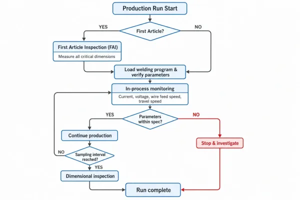
A process control workflow for robotic welding production, showing the sequence from first article inspection through continuous parameter monitoring to periodic dimensional checks.
A correctly designed part, a precision fixture, and a programmed robot establish the baseline. Process control maintains it. Over a production run—and across repeat orders—several variables can drift and affect assembly consistency.
First Article Inspection (FAI). The first article is the reference point. Before full production begins, the first welded assembly should be inspected against all critical dimensions: hole positions, frame squareness, door gaps, flatness, and weld appearance. This confirms that the design, fixture, and welding parameters produce an acceptable result. FAI should be mandatory for every new part and for any repeat order where the fixture has been serviced or the material source has changed.
In-process monitoring. Modern robotic welding systems can log welding current, voltage, wire feed speed, and travel speed for each weld. These parameters can be reviewed to confirm that the process remained within specification throughout the production run. For critical assemblies, this data provides production traceability and early warning of drift.
Incoming material variation. Even within specification, material properties can vary between batches. A different heat of steel, a different coil of aluminum, or a sheet from a different supplier may behave slightly differently under the welding arc. Controlling this variable requires material traceability—mill test reports (MTR) linked to each production batch—and, for critical parts, weld procedure qualification on the actual incoming material.
Inspection frequency. For repeat production, dimensional inspection of every part is rarely practical. A sampling plan—check every Nth part, or inspect critical dimensions at the start and end of each shift—balances quality assurance with production efficiency. The sampling frequency should be based on the criticality of the dimensions and the historical consistency of the process.
How to Evaluate a Supplier’s Robotic Welding Repeatability
When sourcing welded sheet metal assemblies from a supplier with robotic welding capability, the following questions can help determine whether their process will deliver the consistency your product requires:
- Do you use dedicated fixtures for repeat production? Dedicated fixtures indicate a commitment to positional consistency. If the answer is “we adjust the fixture each time,” expect more variation.
- What is your first article inspection process? A structured FAI process—with documented dimensional results—is the minimum standard for confirming that the setup produces acceptable parts.
- Do you log welding parameters during production? Parameter logging enables traceability and early detection of process drift. Suppliers who cannot show you their welding logs may not be monitoring the process closely.
- How do you control incoming material quality? Material traceability through MTRs and thickness verification at incoming inspection are indicators of a controlled supply chain.
- What dimensional tolerances can you consistently hold on welded assemblies? A supplier who can quote specific tolerance ranges—based on their actual production data—is more reliable than one who says “we can hold whatever you need.”
These questions do not require the supplier to reveal proprietary process details. They are standard engineering checks that separate suppliers with genuine repeatability capability from those who have a robot but have not built the supporting system around it.
When Robotic Welding Does Not Improve Repeatability
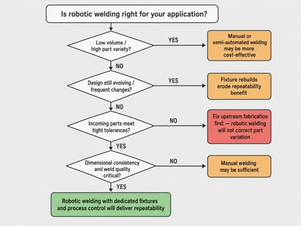
A decision flowchart guiding engineers through four key questions — volume, design stability, incoming part quality, and criticality — to determine whether robotic welding is the right approach for their sheet metal assembly.
Robotic welding is not the right answer for every situation. In some cases, the investment in automation does not translate into better assembly consistency:
Low volume with high part variety. If production involves small batches of many different assemblies, the time and cost of building and maintaining dedicated fixtures for each part may not be justified. Manual welding or semi-automated welding with simpler fixturing may deliver acceptable consistency at lower cost.
Frequent design changes. If the assembly design is still evolving—through prototyping, field testing, or customer feedback—the fixture will need to be modified or rebuilt with each change. This erodes the repeatability benefit and increases cost.
Poor incoming part quality. If the upstream processes—laser cutting, bending, stamping—produce parts with large dimensional variation, robotic welding will not correct the problem. It will reproduce it consistently. Fixing the upstream process should come before investing in welding automation.
Non-critical weld aesthetics or strength. For assemblies where weld appearance and precise dimensional control are not critical—such as internal structural brackets that are never visible—the consistency advantage of robotic welding may not justify the setup cost.
In these scenarios, the most practical path to consistency may be improving the manual welding process, investing in better upstream fabrication, or using semi-automated welding fixtures that provide some of the positioning benefits without the full automation investment.
FAQ
If you are evaluating robotic welding for a sheet metal assembly and want to understand whether your part design and tolerances are a good fit for automated welding, our engineering team can review your drawings and provide a DFM assessment focused on weldability and assembly consistency. Upload your drawings for a review →