
A sealant bead can look smooth, run dead-straight along the joint, and still leak the moment the enclosure sees pressure or weather. Visual neatness describes the outer skin of the bead; it says almost nothing about whether the seal is unbroken along its full length or bonded to both faces of the joint. Continuity inspection — the set of checks that verifies there is no open path through or along the bead — closes that gap between appearance and sealing performance. On production parts, it works only when the method and the pass/fail limits are agreed before the first part ships.
What “Continuous” Really Means on a Sealant Bead
In inspection terms, a continuous bead is one that leaves no open path from one side of the joint to the other. The definition is functional, not aesthetic: a bead can be slightly wavy or vary in color and still pass, provided the seal itself is unbroken. Four defect forms break the requirement:
- Gap — a stretch of joint where the bead is missing entirely. It is the most visible failure and the easiest to catch, and it usually points to a start-stop error or a skipped section.
- Void — a bubble or hollow inside the bead that removes material from part of the cross-section. The surface may look perfect; the leak path is internal.
- Neck-down — a section where the bead narrows below the specified width or height, often where the applicator changed speed or crossed a feature. A thin section can pass a glance and still fail under pressure.
- Edge lift (loss of wetting) — the bead is present but not bonded to one of the substrate faces, leaving a micro-channel along the interface. This is the defect most often missed by both eyes and fingers.
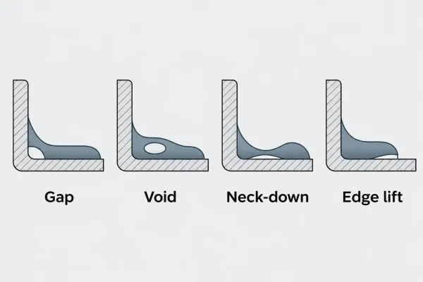
Four defect forms that break bead continuity: gap, void, neck-down, and edge lift.
Most disputes over “was the bead continuous?” are really disputes about which of these four defects the acceptance rule was meant to cover.
Why a Continuous-Looking Bead Still Leaks
Surface checks report on the surface. A gloved finger confirms that the bead feels unbroken; it will not detect a void under the skin or a poorly wetted edge hidden at the fillet. When the requirement is a sealed enclosure — an IP rating, a pressure boundary, a contamination barrier — that difference is exactly where the leak starts.
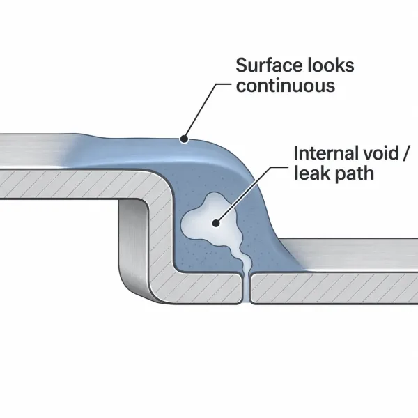
A bead can present a smooth continuous surface while an internal void leaves an open leak path.
Where the breaks come from on sheet metal parts
On sheet metal assemblies, continuity defects rarely distribute at random. They concentrate where geometry and process sequence make a clean, steady pass difficult:
- Joint gaps and fit-up. A visible gap between flanges forces the bead to bridge rather than bond, and bridged sections void as they cure.
- Corner geometry. Inside corners and weld transitions change the applicator angle mid-pass; speed drops or rises, and the bead necks down or piles up.
- Surface preparation. Oil, drawing residue, or an unprepared coating edge prevents wetting. The bead looks attached but peels as a continuous ribbon when pulled.
- Cure and handling sequence. Welding or handling after application, or applying over a still-outgassing surface, locks in voids that no inspection of the cold bead will explain.
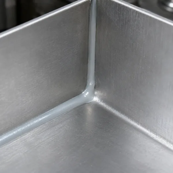
Inside corners and weld transitions change applicator angle mid-pass — a common origin of neck-down defects.
These are process facts, not inspection failures — which is why continuity criteria imposed without a process conversation rarely hold up in production.
Inspection Methods That Actually Prove Continuity
Each method proves a different part of the claim. Building an inspection stack means deciding which defects you are actually trying to exclude.
Visual and dimensional inspection is the baseline. Under adequate light, the inspector looks for open gaps, surface voids, and start-stop irregularities, then measures bead width and height against the drawing at defined points. At 100% coverage it catches every surface-breaking defect — and none of the internal ones.
Tactile checks — running a finger or a blunt probe along the bead — add confidence on surface breaks and gross voids. They are fast and nearly free, and they are also the check most likely to be recorded as “OK” on a defect that a leak test would reject.
Pressure and vacuum leak testing
These methods test the seal the way the part will be used. Pressure decay, bubble immersion, or vacuum decay measures whether any open path exists across the joint, regardless of what the bead looks like. For enclosures with an IP rating or a pressure requirement, a leak test is the only method that proves the functional claim directly — visual inspection alone never does. Coverage runs from sample-based on stable processes to 100% on critical seals.

Pressure decay testing checks whether any open path exists across the joint, regardless of bead appearance.
Ultrasonic and dye methods
Ultrasonic scanning detects subsurface voids and unbonded edges by reading how sound travels through the bead and interface. Fluorescent dye penetrant highlights surface-breaking channels the eye misses under ordinary light. Both are typically applied to high-risk joints, first articles, or failure investigations rather than to every part: they answer “where exactly is the break?” after a leak test has already answered “is there one?”
Choosing Between Methods: Coverage, Cost, and Risk
The right combination depends on what the bead must seal and what a miss would cost. The table below maps each method to what it proves and where it fits.
| Method | What it proves | Typical coverage | Fits when |
|---|---|---|---|
| Visual & dimensional | Surface continuity; bead width/height vs. spec | 100% (practical) | Every part, as the baseline screen |
| Tactile check | Surface breaks, gross voids | Sampling | Quick in-process screen on stable geometry |
| Pressure / vacuum leak | Functional seal — no open path across the joint | Sample to 100% | IP-rated or pressure/contamination enclosures |
| Ultrasonic | Subsurface voids, unbonded edges | Sampling | High-risk joints, first articles, failure analysis |
| Dye penetrant | Surface-breaking gaps and channels | Sampling | Post-process checks on suspect areas |
A practical rule of thumb: if a leak would create a warranty, safety, or contamination event, pay for a functional leak test and keep visual inspection as the 100% screen underneath it. If the bead is primarily cosmetic or dust-protective, visual plus dimensional checks at defined sample points are usually proportionate.
Acceptance Criteria That Make Pass/Fail Objective
“Continuous” as a bare word gives the inspector nothing to sign. A usable acceptance rule puts numbers on four things:
- Maximum allowable gap. For IP-rated or pressure seals, the honest number is zero open gap along the joint. For non-critical joints, a stated maximum (for example, no single gap over 2 mm, none within 25 mm of a corner) at least makes the judgment repeatable.
- Bead width and height range. Neck-down is a continuity defect only relative to a spec; the drawing should state nominal plus tolerance (width 6 ±1 mm, for instance).
- Coverage. The bead must cover the joint over its full defined length. Partial coverage is a gap even when the material present looks healthy.
- Functional tie-in. Criteria should reference what the bead seals — an IP class, a pressure value, a cleanliness requirement — so that severity and sampling level follow the consequence of a miss.
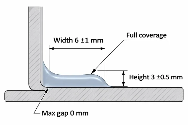
Acceptance criteria put numbers on bead width, height, coverage, and maximum allowable gap.
One judgment worth stating plainly: tightening a cosmetic bead to zero-gap leak-test standards adds cost with no functional return, and loosening a pressure seal’s criteria to “visually continuous” relocates the problem to the customer. Match the number to the function.
Specifying Continuity Inspection on Drawings and RFQs
A complete callout answers four questions before production starts: method (visual, leak test, ultrasonic), acceptance criteria (the numbers above), sampling plan (100%, or lot size and frequency), and disposition (what happens to a nonconforming part — rework, scrap, or as-is with concession). Written together in the drawing’s notes or the RFQ quality section, these four elements let the fabricator quote the inspection honestly instead of absorbing it.
What happens when the drawing is silent
If the drawing says only “sealant applied continuously” or “seal the joint,” the shop defaults to its cheapest reasonable interpretation: a quick visual pass at the end of the line. That default is not negligence — it is what the document asked for. The cost surfaces later, as a leak test nobody quoted, a rejection against criteria nobody wrote down, or an argument over whether a 40 mm visible gap on a dust cover is a defect. All three are cheaper to prevent at the RFQ stage than to resolve at receiving inspection.
Where to Check: FAI, In-Process, and Final Inspection
Continuity is worth verifying at three points, and each point proves something different. First Article Inspection (FAI) proves that the method and the criteria work on real parts — that the leak tester detects the smallest gap you care about, and that the bead process can hold the width spec. In-process checks catch drift: adhesive condition, applicator wear, fixture changes, and operator changeover all move bead quality after the first article is approved. Final inspection confirms that what ships meets the agreed rule — functionally (leak test) on critical seals, visually and dimensionally on lower-risk joints.
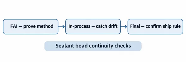
Continuity is verified at three stages: FAI proves the method, in-process catches drift, final confirms the shipping rule.
From sample order to production
On a sample order, inspect more aggressively than you plan to in series production: run the leak test at 100%, measure bead dimensions at several positions, and cross-check suspect areas once with dye or ultrasonic to see what the process is actually capable of. What you learn there sets the sampling plan you can defend in the purchase order. In stable series production, 100% visual plus a defined leak-test sample (per lot or per shift) is a common balance; tighten to 100% functional testing when a single escape would create a safety or contamination event.
FAQs
Checklist: What to Put in the RFQ
Before the next quote package goes out, the continuity requirement should state:
- What the bead seals (IP class, pressure, contamination level)
- Which defect types are not accepted (gap, void, neck-down, edge lift — as applicable)
- Quantitative limits (maximum gap length, bead width/height tolerance, coverage)
- Inspection method and sampling plan (100% visual; leak test per lot; etc.)
- Disposition rule for nonconforming parts (rework / scrap / concession)
If these five items are on the document when quotes come back, the inspection is priced, the acceptance is objective, and the conversation at receiving is about evidence instead of interpretation. A quick manufacturability and quality-plan review before RFQ release is the cheapest place to settle them.