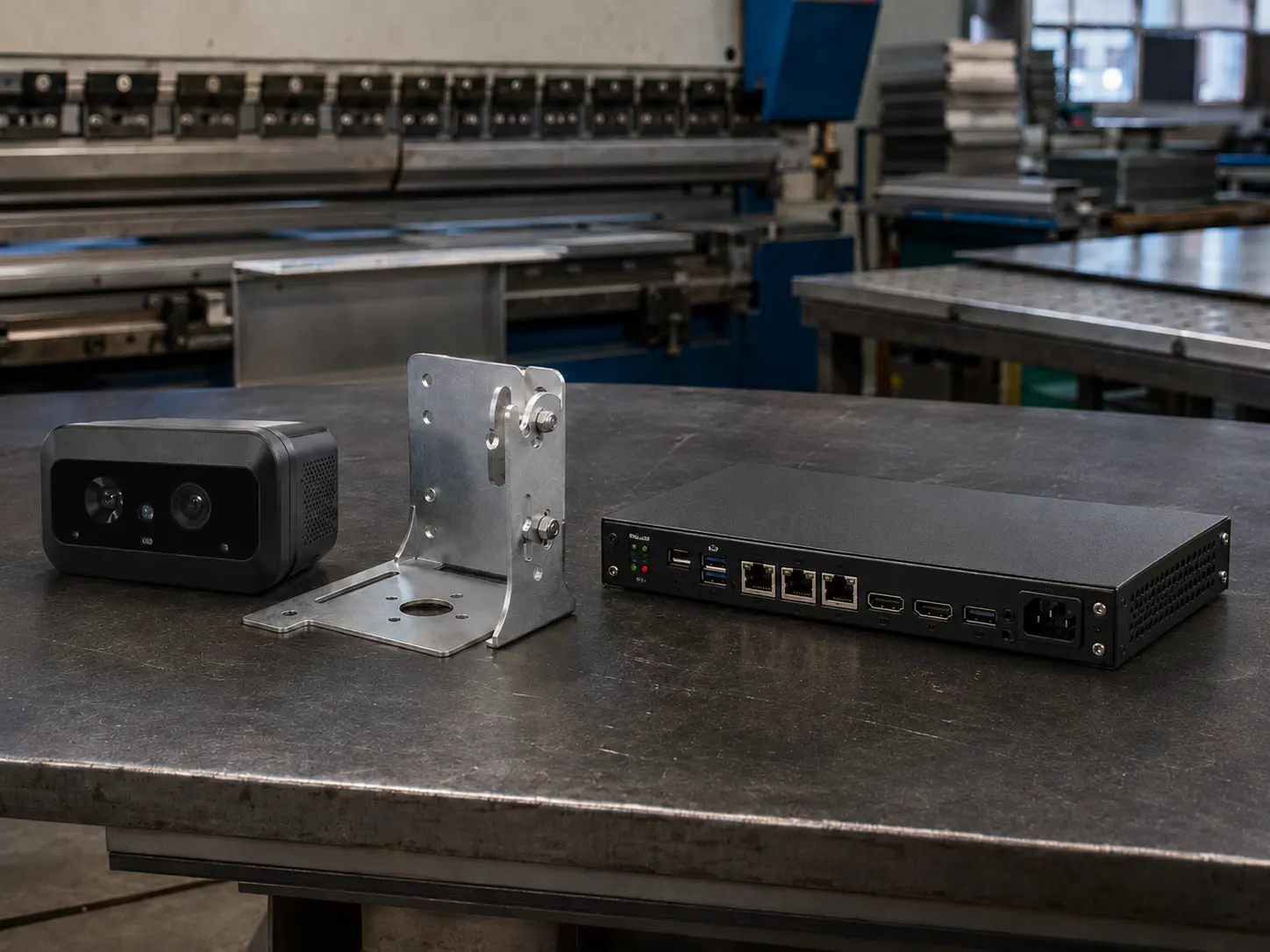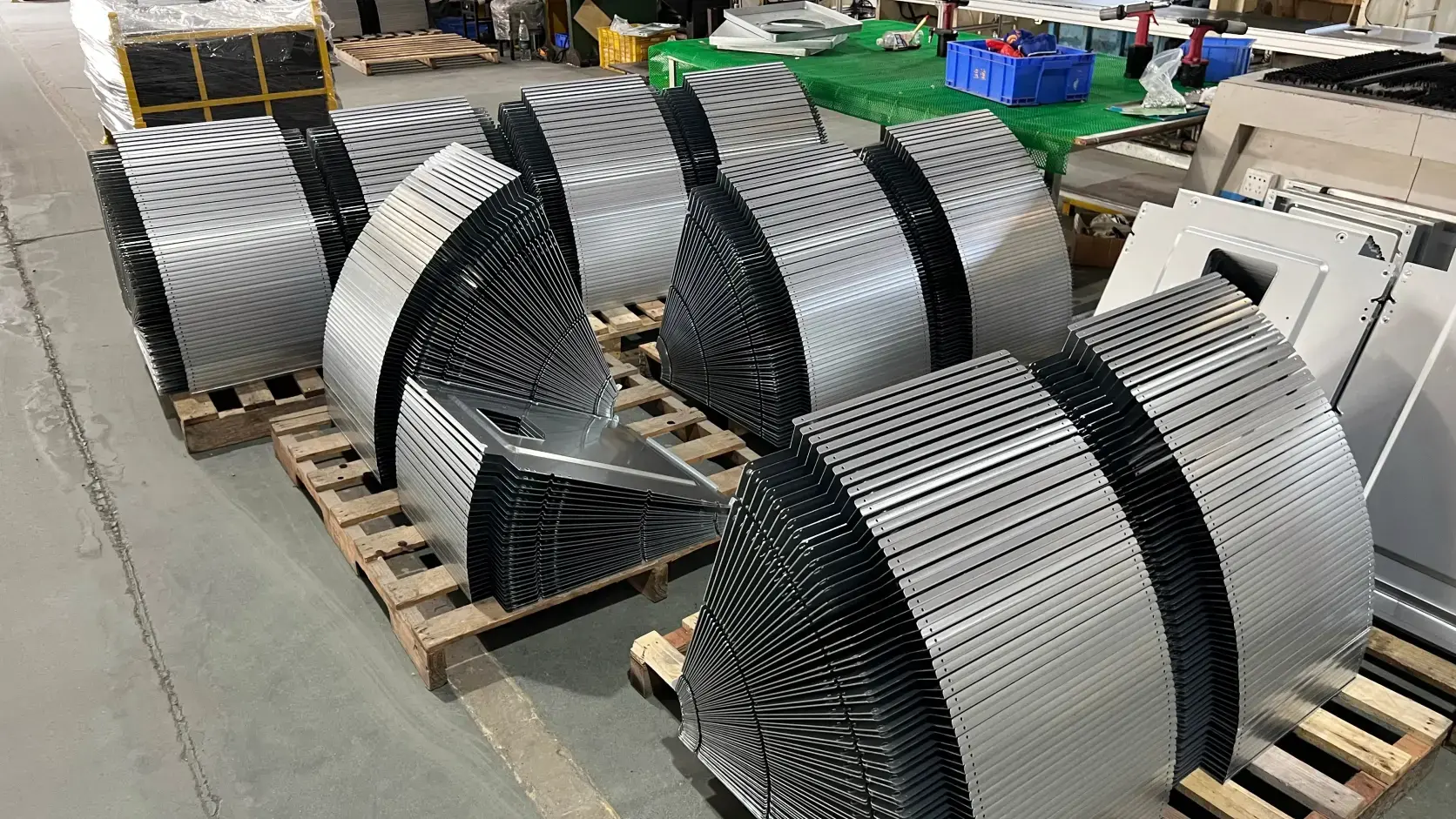

A sheet metal bracket that looks straightforward on screen — one flat pattern, a single material, moderate size — comes back from quoting with a four-week lead time. The material is not the reason. The reason is the number and difficulty of manufacturing operations the part demands: bends that change direction, welds in tight corners, inserted hardware, and a tolerance class that forces extra inspection. In custom manufacturing, this hidden workload is called process complexity, and it is one of the most reliable predictors of how long a part will take to produce.
What Process Complexity Means for a Single Part
Process complexity, at the part level, is the total count and difficulty of the manufacturing operations required to turn a raw sheet or blank into a finished, inspected component. It is not a project-management buzzword and not a factory-wide efficiency metric. For a single part, it answers one concrete question: how many distinct steps must happen, and how hard is each one?
This definition matters because most public content about “process complexity” addresses enterprise topics — organizational overhead, ERP systems, or business-process management. An engineer or buyer searching for the term usually needs something narrower: why one drawing takes two weeks and another takes six. Part-level process complexity fills that gap. It is measurable from the drawing and the bill of process, before any material is ordered.
The Five Dimensions Behind a Part’s Process Complexity
Part-level process complexity is not a single score. It accumulates from five independent dimensions, each visible on the drawing or in the routing.
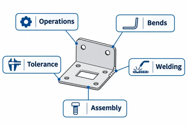
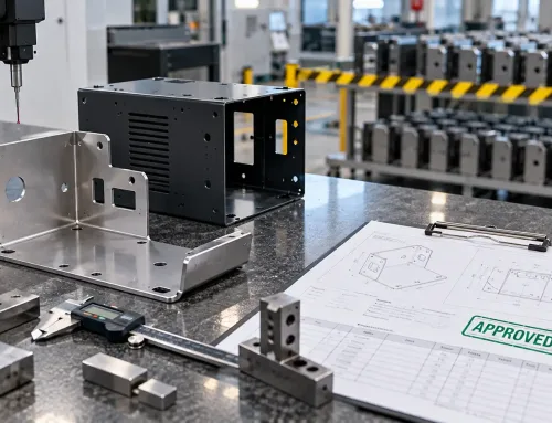
The five dimensions of part-level process complexity and the drawing features that signal each one.
The table below summarizes the five dimensions and the drawing features that signal them.
| Dimension | What raises it on the drawing | Typical time effect |
|---|---|---|
| Operation count | More process steps (cut → form → weld → finish → inspect) | More setup and transfer time |
| Bend count and direction | Many bends, alternating flange directions | Programming and first-article time |
| Welding and joining | Long or positional welds, multiple joint types | Fixture time and skilled-labor hours |
| Assembly and hardware | Press inserts, fasteners, sub-assembly steps | Per-unit labor and inspection |
| Tolerance and inspection | Tight GD&T, many critical dimensions | Inspection time and rework exposure |
Operation count and routing length
Every additional operation on the process route adds a setup event, a handling event, and a queue interval. A part that requires cutting, forming, welding, grinding, and powder coating has five stations; a part that can leave after cutting and forming has two. The three extra stations do not just add shop hours — they add calendar days, because each station may run in a different batch window.
Bend count and direction changes
Bends are among the most time-intensive forming operations in sheet metal. Each bend requires a press-brake setup (punch and die selection, backgauge programming) and, for tight or multi-bend parts, a first-article check. Parts with eight or more bends, or with bends that alternate between two flange directions, can require multiple setups or even different tooling sets.
Welding and joining requirements
Welding adds time in three ways: fixture design and loading, welder skill allocation, and post-weld inspection or grinding. A continuous seam weld around an enclosure takes longer than four tack welds. Positional welds (vertical or overhead) slow the operator further. When two different joining methods appear on one part — say, spot welding plus hardware insertion — the routing branches and scheduling becomes harder.
Assembly steps and inserted hardware
Press-fit fasteners (PEM-style studs, nuts, or standoffs) each add a press operation and a pull-test or torque-check sample. Multi-part assemblies add matching, alignment, and sub-assembly inspection. A bracket that needs twelve inserts and two riveted sub-components carries a higher process complexity than a single-piece bracket of the same material and weight.
Tolerance class and inspection load
Tight tolerances do not change the forming time dramatically, but they change the inspection time and the probability of rework. Every dimension marked with a tight tolerance — or with a geometric callout such as true position or flatness — becomes a measured characteristic on the inspection report. When a drawing calls out fifteen critical dimensions instead of three, the inspection stage can take twice as long, and the chance of finding a nonconformance rises.
How Each Dimension Adds Manufacturing Time
The five dimensions above affect lead time through three mechanisms: setup and programming, queue and transfer, and inspection and rework.
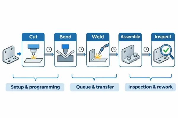
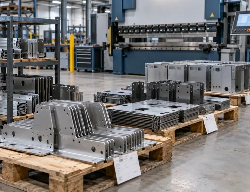
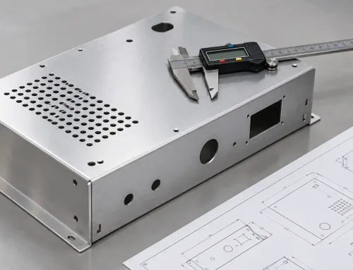
How process complexity adds manufacturing time at every station — setup, queue, and inspection.
Programming, setup, and first-article time
Each new operation requires a setup event. On the press brake, every bend program needs verification. On the welding fixture, each joint type needs a load-and-check cycle. For low-volume or first-time parts, first-article inspection (FAI) is mandatory at each critical stage. A part with four process stages and twelve bends can easily consume a full day of setup before production begins.
Queue time and handling between operations
Parts do not move instantly from one station to the next. They wait in a queue for the next available machine or operator window. In a busy shop, each handoff can add one to three days of queue time. A part routed through five stations therefore accumulates four queue intervals — potentially a week or more of pure waiting — even when the actual machining time is only a few hours.
Inspection load and rework exposure
Every critical dimension must be verified. Complex parts generate more inspection steps and a higher probability of finding a deviation, which triggers rework or scrap. This is why two parts with identical material and blank size can have very different lead times: the part with more bends, a weld seam, and tighter tolerances must survive more checkpoints.
How to Read Process Complexity from a Drawing
Before requesting a quote, an engineer can estimate a part’s process complexity by scanning the drawing for five signals:
- Operation count — count the distinct process steps implied by the geometry and finish callouts. Four or more stages (cut, form, weld, finish) means a longer routing.
- Bend count and direction — number the bends and check whether they alternate between flange directions. Six-plus bends or alternating directions raise setup time sharply.
- Welding symbols — continuous or positional weld symbols indicate fixture time and skilled labor. Multiple joint types on one part add routing branches.
- Hardware callouts — each press-insert or fastener adds a press operation and a sample check. Count them.
- Critical dimensions — identify how many dimensions carry tight tolerances or geometric callouts. More than five critical characteristics means a heavier inspection load.
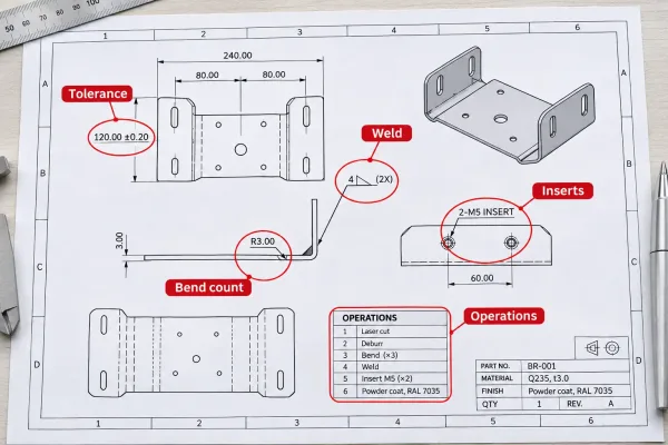
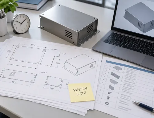
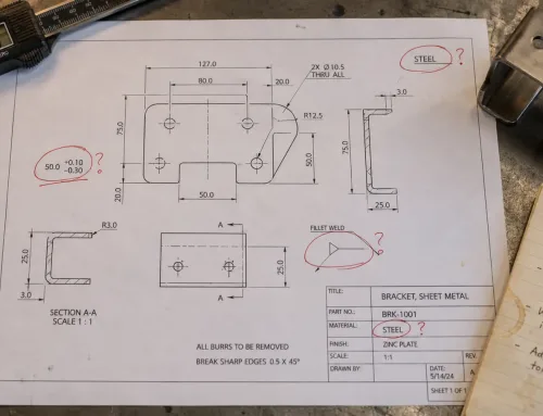
Five drawing signals that indicate a part’s process complexity before quoting.
A part that triggers three or more of these signals is a high-process-complexity part. Flagging it early allows realistic lead-time planning and avoids quoting surprises.
What to Change Before RFQ to Keep Lead Time Realistic
Not every source of process complexity is functional. Some are design habits that can be relaxed without affecting fit or performance. Before sending the RFQ, consider these checks:
- Separate functional tolerances from default ones. Ask whether each tight tolerance protects a mating surface, a seal, or a safety-critical dimension. Tolerances that do none of these can usually be opened to standard sheet-metal capability.
- Consolidate bend directions where possible. Reducing direction changes on the press brake can eliminate a second setup. Even one fewer setup saves a batch-window wait.
- Merge or eliminate secondary operations. If a weld seam exists only for sealing, consider whether a folded-and-seamed joint or a gasket groove could replace it. Fewer joining methods means a shorter routing.
- Specify inspection load explicitly. If only three dimensions are truly critical, say so on the drawing. Specifying “inspect all dimensions” on a complex part inflates inspection time and cost.
- Include process notes in the RFQ. A short note listing intended process sequence or acceptable alternatives gives the fabricator room to optimize the routing without guessing.
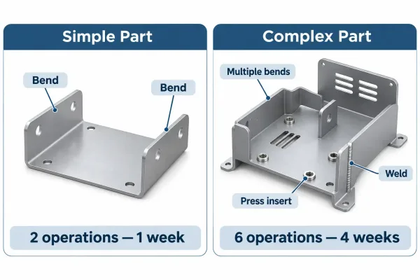
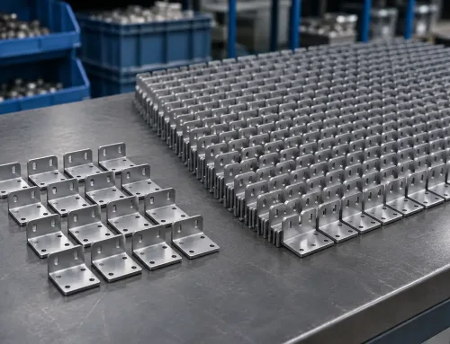
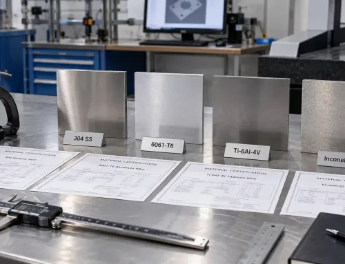
Two parts of similar size and material — different process complexity means very different lead times.
These actions do not reduce part function. They reduce the number of unnecessary setups, checks, and queue intervals — which is exactly what keeps lead time predictable.
For the next quotation, try this: before uploading the drawing, run the five-signal scan above and note which signals are functional and which are optional. That single exercise, done at design release, prevents most of the lead-time surprises caused by process complexity.