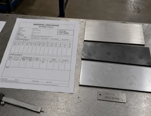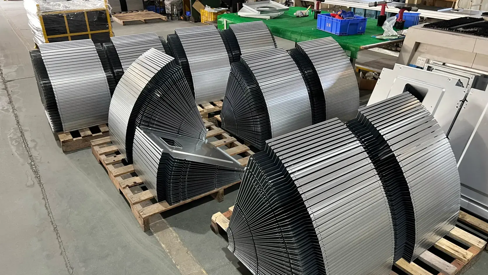

A flatness callout in the feature control frame — the box on a drawing that holds geometric tolerances — is easy to file under “already handled.” On sheet metal work, that shortcut misses half the requirement. Material flatness, the shape condition of the sheet before anything is cut, and the flatness tolerance of a finished part surface are two different things. They are measured at different stages, controlled by different documents, and owned by different parties. Confuse them, and the problem surfaces late: warped blanks, shifting bend angles, and gaps at assembly.
Why Material Flatness Is Not the Same as Flatness Tolerance
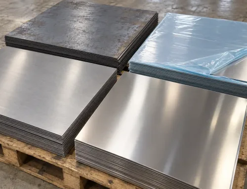
Material flatness describes the incoming sheet or plate: how far its surface deviates from an ideal plane before any processing. It is a supply property, checked at receiving, and governed by material specifications such as EN 10029 for hot-rolled plate or ASTM B209 for aluminum sheet and plate.
A flatness tolerance on a part drawing is a different requirement. It is a geometric condition on a finished surface or feature, defined as a zone between two parallel planes that the surface must stay inside. The drawing controls the part. The material specification controls the stock.
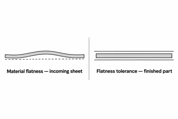
Material flatness governs the incoming sheet; drawing flatness tolerance governs a finished part surface.
The two requirements differ in four practical ways:
| Material flatness | Drawing flatness tolerance | |
|---|---|---|
| What it controls | Incoming sheet surface | Finished part surface or feature |
| When it is checked | Receiving inspection | Final or in-process inspection |
| Where it is written | Material spec, purchase order notes | Drawing, feature control frame |
| Who owns it | Mill, service center, or whoever ships the stock | The fabricator producing the part |
The two do not guarantee each other. A sheet can arrive within its material flatness limit and still release enough residual stress after cutting for the part to fail the drawing callout. A wavy sheet can also yield compliant parts once it is clamped, cut, and formed. Each requirement has to be stated on its own.
What Material Flatness Actually Measures
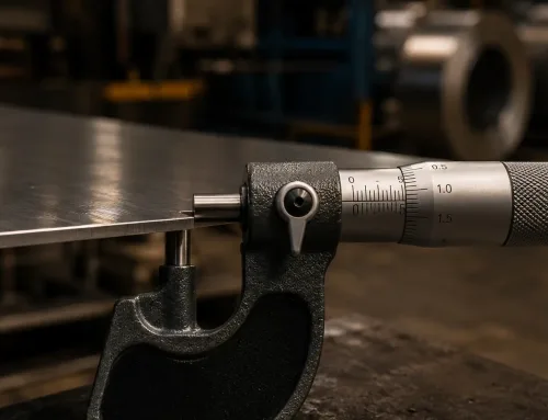
In measurement terms, material flatness is the gap between the highest and lowest points of the sheet surface relative to a reference plane, evaluated over a defined length. It is expressed as a deviation per unit length — millimeters per meter (mm/m) or inches per foot (in/ft) — not as a single absolute figure.
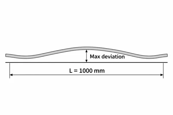
Flatness is read as the maximum deviation from a reference plane over a stated length.
The length basis carries meaning. A sheet can hold within tolerance over any one-meter span and still carry a slow wave across a six-meter length, so a flatness figure without its length is not a specification.
Tolerance values come from the applicable material standard and shift with alloy, thickness, and width. Two sheets of the same grade can therefore carry different limits and both be correct, which is why the purchase order should name the standard it expects.
What Causes Incoming Sheet to Lose Flatness
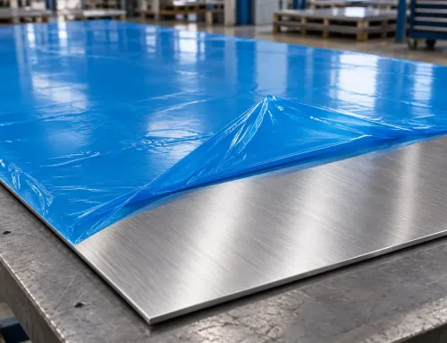
Sheet rarely leaves the mill perfectly flat. Rolling and leveling operations leave residual stress — internal stress that remains after forming — locked into the material. When a sheet is cut free of the surrounding web or released from a coil, that stress redistributes and the sheet moves. Coil set, a curl carried over from storage in coil form, is common in thin and cold-rolled stock. Edge wave and center buckle come from roll crowning and strip tension during rolling: edges longer than the center produce wavy edges, while the reverse produces a buckle.
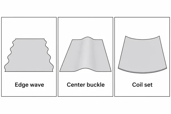
Edge wave, center buckle, and coil set — the three out-of-flat shapes most often seen in sheet stock.
Handling adds to the effect. Thin sheets stacked without support, uneven resting points, and temperature swings all push shape out of tolerance. Risk peaks on wide thin sheet, on coil-supplied material that has not been leveled, and on large blanks cut from the middle of a stressed sheet.
How Out-of-Flat Stock Affects Cutting, Bending, Welding, and Assembly
One shape error does not fail in one way. Each fabrication step converts it into a different defect.
Laser Cutting
Laser cutting assumes the sheet lies flat on the bed. Where the sheet lifts, standoff distance — the gap between the nozzle and the sheet — changes, focus drifts, and edge quality drops along the cut. After the contour closes, released stress can twist the blank away from the flat pattern, and the part that matched the drawing on screen measures out on the bench.
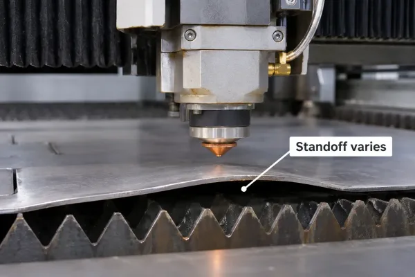
Where a sheet lifts off the cutting bed, the laser nozzle standoff changes along the cut.
Bending
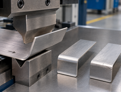
Bending assumes a flat, square blank. A wavy blank meets the backgauge — the movable stop that positions the sheet in the press brake — unevenly, so flange lengths and bend angles shift across the same part or across a batch. Springback also tracks the stress state of the sheet, so a bend program tuned on flat stock drifts on wavy stock.
Welding
Weld fit-up depends on two edges meeting along the same line. Out-of-flat panels leave gaps that vary along the seam, tack welds pull the assembly toward the stiffer side, and welding heat adds distortion on top of the shape error already present. Seams that look acceptable in the fixture can open once the assembly is released.
Assembly
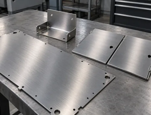
Assembly is where shape error becomes visible to the customer. Holes that lined up in CAD miss by fractions of a millimeter, mating faces gap, and fasteners bind or strip. A part can pass dimensional inspection feature by feature and still fail at fit.
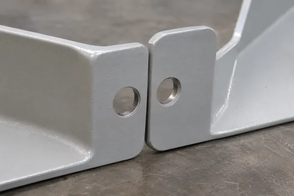
Out-of-flat stock shows up at assembly as misaligned holes and gaps between mating faces.
How to Specify Material Flatness on RFQs and Drawings
Keep the two requirements in two places. The drawing carries the part’s flatness tolerance in the feature control frame. Material flatness belongs in the material specification, purchase order notes, or a drawing note that refers to the stock — for example, “sheet flatness ≤ 1.5 mm/m per EN 10029, measured on incoming material.”
A complete callout states three things:
- The deviation limit, meaning the maximum allowed.
- The length the limit applies to.
- The standard or measurement basis the supplier is expected to use.
Adding surface condition — as-received, leveled, dry — removes assumptions, especially when parts are cut from a larger sheet. If the drawing is still open, this is also the cheapest point to reduce risk: a manufacturability review before release flags part geometry that will not hold flatness even from good stock.
Incoming Inspection and Disposition When Stock Fails
Incoming flatness checks are simple to run. A straightedge and feeler gauge over the length of interest, a surface plate with a height gauge, or a three-point setup with a dial indicator will resolve most acceptance questions. Optical and laser methods are reserved for large plates or tighter limits.
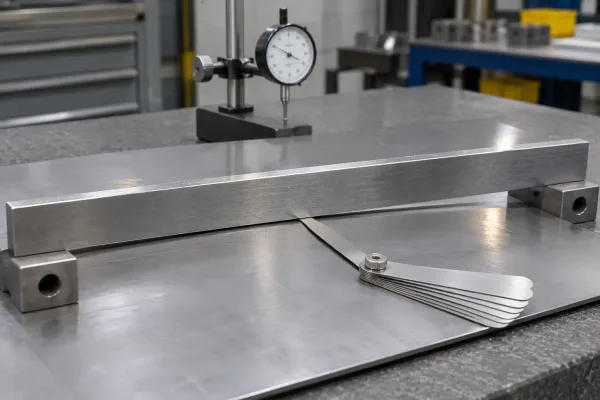
A straightedge and feeler gauge resolving the flatness gap on an incoming sheet.
When stock falls outside the limit, three dispositions are practical. Leveling — roller or tension leveling, which relaxes stress by stretching the sheet through rolls or under tension — restores flatness but adds cost, lead time, and a possible change in surface condition. Acceptance with a concession works when the out-of-flat area will be cut away or the affected features are non-critical. Rejection and return fit cases where flatness feeds visible panels or mating interfaces and no later step will correct it.
The disposition is easy only when the requirement was written down. Flatness that exists solely as an assumption is a dispute waiting for the first bad assembly.
FAQs