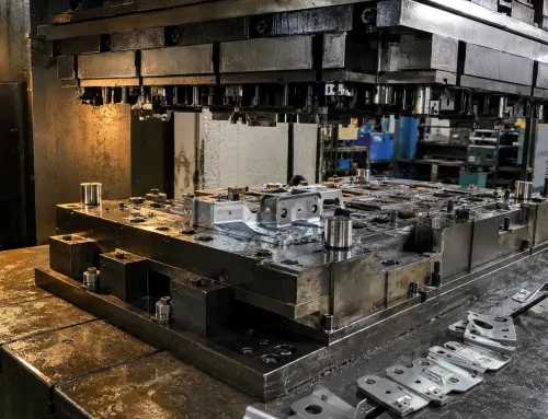
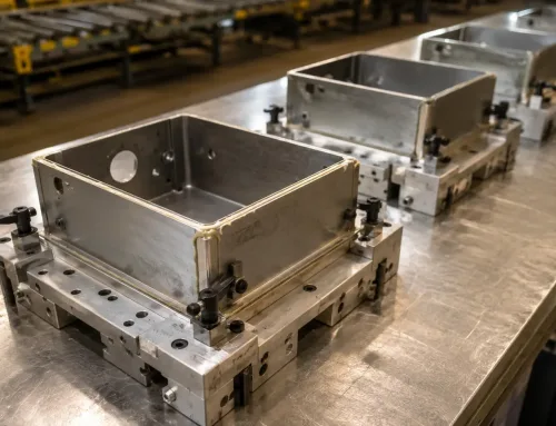
Whether you are a purchaser or the person responsible for an entire sheet metal project, you need to understand how custom sheet metal brackets go through review, fabrication, inspection, surface finishing, and the complete manufacturing process before production begins.
A sheet metal bracket is a formed metal part mainly used to support, connect, or position other metal components. It can be a simple L-shaped part, or it can be a mounting bracket with multiple bends.
Although a bracket may not look complicated, its manufacturing quality still depends on the sheet metal factory’s production experience in custom sheet metal fabrication and its quality control.
For engineers and purchasing teams, understanding the sheet metal bracket manufacturing process can help you reduce drawing revisions, quotation communication delays, and a series of related problems.
This article will explain in detail the full manufacturing process of custom sheet metal brackets, from engineering review to finished product delivery, and will also cover several aspects such as design and material selection.
What Is a Sheet Metal Bracket?
A sheet metal bracket is a metal part made from flat sheet metal through cutting, bending, and forming, sometimes combined with welding or hardware assembly, to provide support or connection. It is generally used to mount panels, support frames, fix sensors, or connect different parts inside industrial equipment.
Compared with machined parts or cast parts, the advantages of sheet metal brackets are that they are lighter, easier to customize, and more suitable for mass production. A properly designed metal bracket can provide more reliable support with less material and a more stable manufacturing route.
Many custom brackets are produced according to 2D drawings, 3D CAD models, or a combination of both. However, it should be noted that details such as bend radius, flange length, hole-to-bend line distance, and tolerance notes may directly affect forming accuracy and final assembly fit.
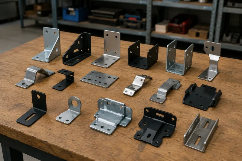
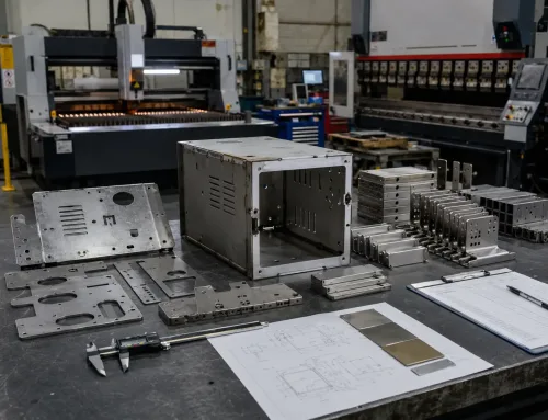
A range of custom sheet metal bracket types manufactured through laser cutting and press brake bending, suitable for mounting, supporting, and connecting industrial components.
Why Is Sheet Metal Fabrication More Suitable for Manufacturing Brackets?
In fact, metal brackets are now basically manufactured by sheet metal fabrication, because it can support flexible structures, repeat production, and cost control.
A metal bracket can first be cut from flat metal sheet material into a flat blank, and then processed into the shape shown on the drawing by a CNC automatic bending machine or a manual bending machine.
The sheet metal fabrication process is suitable for both prototypes and orders that require mass production. Small quantities of prototypes can complete design verification through laser cutting and bending. For mass production, stable bending programs and fixtures can be used for production.
The most common reasons for choosing sheet metal fabrication to manufacture brackets are:
- Design flexibility: Holes, slots, tabs, openings, and flange structures can be integrated into the same part.
- Good balance between strength and weight: Formed flanges and reinforcing structures can improve rigidity without using a solid block of metal.
- Good production repeatability: CNC cutting and controlled bending help maintain dimensional consistency.
- Easy assembly: Self-clinching nuts, studs, tapped holes, weld nuts, or other hardware can be completed before delivery.
- Compatible with multiple surface treatments: Brackets can choose powder coating, electroplating, anodizing, brushing, or passivation according to the material and application.
Sheet Metal Bracket Manufacturing Process
The manufacturing process of custom sheet metal brackets in a sheet metal fabrication factory includes drawing review, material selection, cutting, forming, secondary processing, surface treatment, inspection, and packaging. However, the specific process route still needs to be communicated and sampled between the demander and the supplier.
1. Drawing Review and Manufacturability Check
Before production begins, the factory will review the drawings and CAD files to confirm whether the bracket part can be manufactured efficiently and accurately inside the factory. This step can help customers find problems such as unclear dimensions, bending difficulties, and hole position risks.
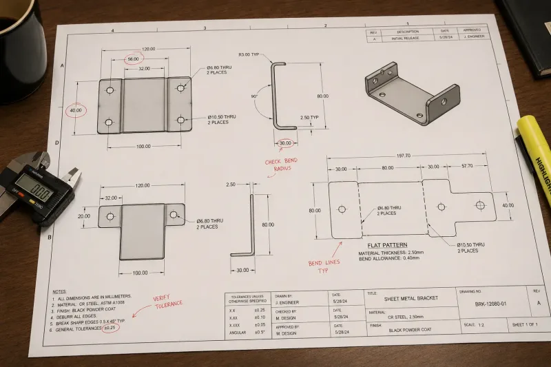
Before production begins, the engineering team reviews the bracket drawing for manufacturability, checking dimensions, bend sequences, hole positions, and tolerance notes to prevent production issues.
2. Material and Sheet Thickness Selection
The material and sheet thickness will affect the strength, forming, surface, and other aspects of the product. Common sheet metal materials for brackets include cold-rolled steel, stainless steel, aluminum sheet, and galvanized steel sheet.
For many customers, the sheet thickness of custom sheet metal brackets is generally between 1.0 mm and 5.0 mm. However, the actual thickness depends on the customer’s requirements. Thicker materials can indeed improve strength, but for processing, they may require a larger bend radius, higher forming force, and attention to springback.
For small electronic equipment mounting brackets, thinner powder-coated steel sheets can be used. However, for cleaning equipment brackets, 304 stainless steel sheet and corrosion-resistant surface treatments are often needed.
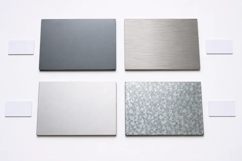
Common sheet metal bracket materials compared side by side: cold-rolled steel, stainless steel 304, aluminum 5052, and galvanized steel — each offering different strength, corrosion resistance, and formability characteristics.
3. Cutting, Punching, and Hole Processing
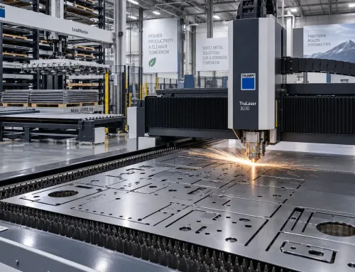
After the material is confirmed, the flat pattern of the bracket will be cut from the sheet metal material by precision laser cutting for sheet metal brackets.
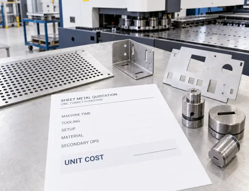
For parts with large quantities or many repeated holes, punching is recommended for consideration.
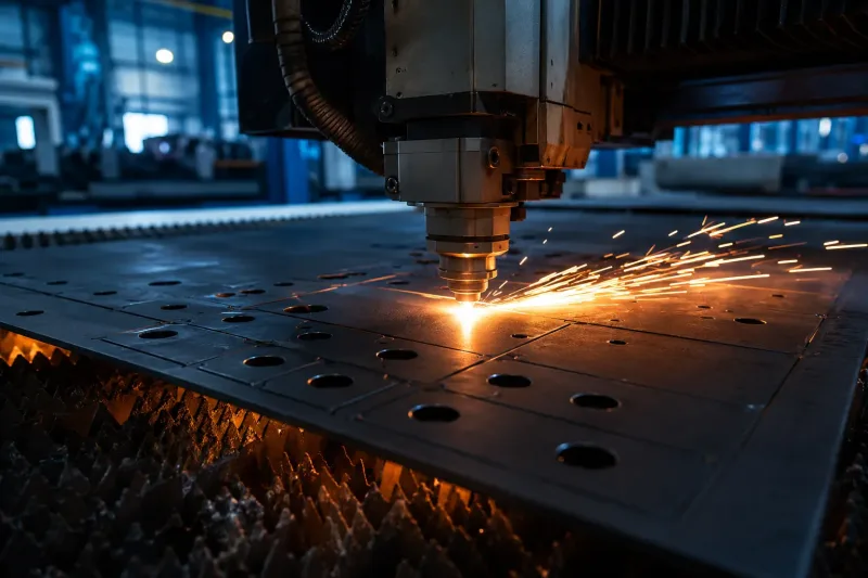
Laser cutting shapes the flat blank pattern from raw sheet material, producing clean edges and precise hole positions that directly affect downstream bending accuracy.
4. Bending and Forming
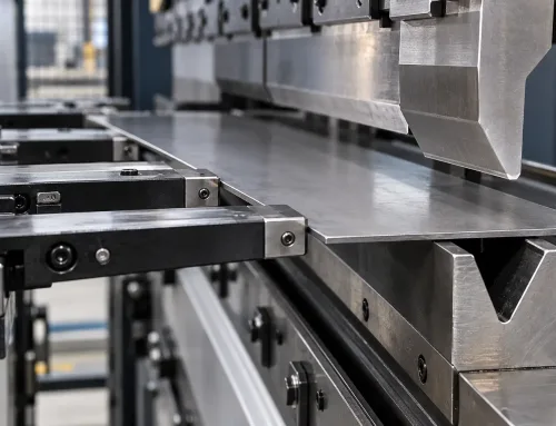
CNC press brake bending turns the flat sheet metal blank into a functional bracket. Pressure is applied to the sheet metal through the upper punch and lower die of the bending machine, forming the angle and bend radius required by the drawing.
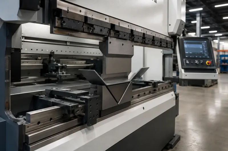
A CNC press brake applies controlled force to form precise bend angles on the flat blank, converting the cut pattern into a functional three-dimensional bracket.
5. Welding, Hardware Installation, and Secondary Processing
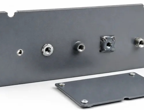
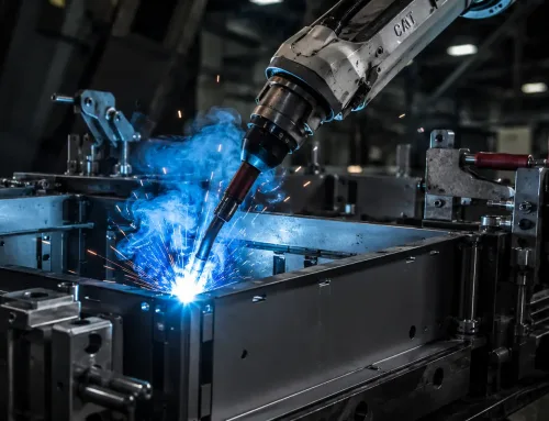
Some brackets may still require secondary processing after cutting and bending. These processes may include welding, self-clinching PEM nut installation, tapping, countersinking, threaded hardware installation, and other operations.Surface treatment can improve the appearance, corrosion resistance, and touch feel of metal brackets. In general, steel brackets use powder coating, small steel parts use zinc plating, aluminum brackets use anodizing, and stainless steel brackets use brushing or passivation.
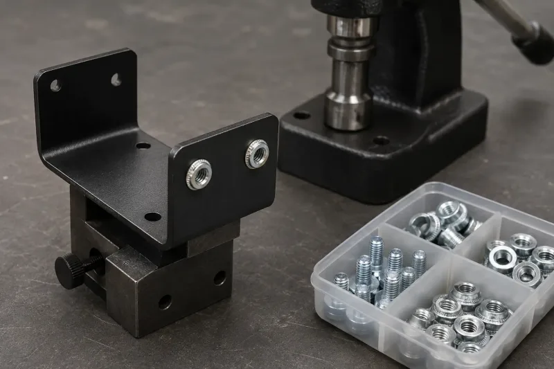
Self-clinching nuts and studs are pressed into pre-cut holes on the bracket, providing integrated threads and mounting points that eliminate the need for separate fasteners during assembly.
6. Deburring, Surface Treatment, and Packaging
After cutting, bending, forming, and secondary processing are completed, the next stage is deburring. Deburring mainly removes the extra material from the edges of the metal bracket to prevent sharp edges from cutting hands. Burrs can also affect coating quality and assembly results.
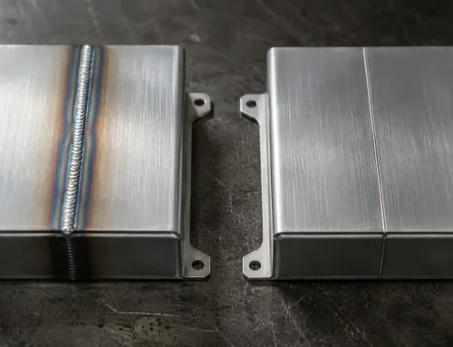
Sheet metal surface finishing can improve the appearance, corrosion resistance, and touch feel of metal brackets. In general, steel brackets use powder coating, small steel parts use zinc plating, aluminum brackets use anodizing, and stainless steel brackets use brushing or passivation.
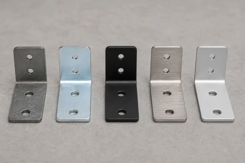
The same bracket design with five different surface treatments — from raw steel to zinc plating, powder coating, brushed stainless, and anodized aluminum — each suited to different environmental and aesthetic requirements.
Packaging is planned according to the final part. For brackets, protective film or foam is generally used as separation to avoid scratches and damage during transportation. Of course, if customers have other requirements, cartons and pallet packaging can also be used.
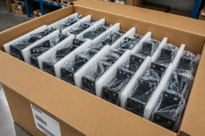
Finished brackets are individually wrapped in protective film and separated with foam dividers to prevent surface damage during storage and transportation.
Common Types of Sheet Metal Brackets and Application Scenarios
There are many styles of sheet metal brackets, but the basic designs are usually based on the following common structures.
| Bracket Type | Common Uses | Manufacturing Notes |
|---|---|---|
| L-shaped bracket | Right-angle mounting, panel support, frame connection | The structure is simple, but hole positions and flange length still need to be controlled |
| U-shaped bracket | Fixing, positioning, clamping, or surrounding other parts | The inner width may be affected by bending tolerance and springback |
| Z-shaped / offset bracket | Creating height differences or aligning mounting surfaces on different planes | Multiple bends can easily cause tolerance accumulation |
| Bracket with reinforcing ribs | Higher load-bearing or anti-vibration structures | Welding, fixtures, and deformation control may be required |
| Custom mounting bracket | Equipment, enclosures, guide rails, sensors, or internal components | Usually depends on the specific CAD file and assembly requirements |
Common applications include industrial equipment, automation systems, electrical enclosures, welded machine base frames, sensor mounts, control cabinets, medical equipment, food processing equipment, and electronic products. Although brackets are only small parts in these industries, they can affect assembly efficiency and the product.
Design Rules for Manufacturable Brackets
The following sheet metal DFM guidelines can ensure that the bracket design can be manufactured efficiently on standard equipment without special tooling or additional processes.
Hole-to-edge distance: The distance between the edge of each hole and the nearest sheet edge should be at least 2 times the material thickness (2t). If the hole is too close to the sheet edge, it may deform during cutting or tear during handling.
Hole-to-bend line distance: The distance between the hole and the bend line should be at least 2t + R or more, where R is the inside bend radius. When the distance is insufficient, material flow during bending can cause the hole to deform or elongate. If the hole must be close to the bend line, the hole can be machined after bending through secondary processing, but this will increase cost.
Minimum bend radius: The inside bend radius should be set to at least 1 times the sheet thickness (1t) for mild steel, and 1.5 to 2 times the sheet thickness for stainless steel and aluminum. A smaller radius carries the risk of cracking on the outside surface of the bend, especially for aluminum alloys with lower ductility.
Minimum flange height: The shortest flange that will not slip out of the tooling is about 4 times the sheet thickness (4t). Shorter flanges require custom tooling or may not be formed cleanly.
Bend reliefs and corner notches: Small bend reliefs or notches should be added where the bend line meets a vertical edge to prevent material tearing during bending. Without bend reliefs, the material has nowhere to flow during bending, which may cause wrinkling or cracking.
The table below summarizes the most common design rules:
| Design Parameter | Minimum Reference Value |
|---|---|
| Hole diameter | ≥ 1t (laser cutting) or ≥ material thickness |
| Hole-to-edge distance | ≥ 2t |
| Hole-to-bend line distance | ≥ 2t + R (inside bend radius) |
| Inside bend radius (mild steel) | ≥ 1t |
| Inside bend radius (aluminum, stainless steel) | ≥ 1.5–2t |
| Minimum flange height | ≥ 4t |
| Slot width | ≥ 1t |
Tolerances in Sheet Metal Bracket Fabrication
The dimensional tolerances of sheet metal fabrication are very different from those of CNC machining, because sheet metal processes involve shearing, thermal cutting, and plastic deformation, rather than removing material from a rigid workpiece. Therefore, the achievable accuracy depends on the specific features, process chain, and skill level.
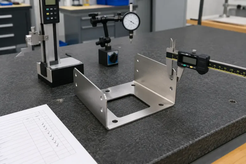
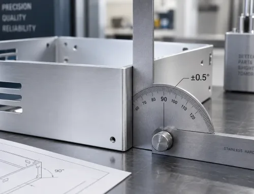
Dimensional inspection of a finished bracket using precision measuring instruments, verifying critical features such as flange height, hole positions, and bend angles against drawing specifications.
The following tolerances represent the standard capability of well-maintained laser cutting and bent bracket production equipment:
| Feature | Standard Tolerance |
|---|---|
| Edge to edge | ±0.13 mm (±0.005″) |
| Edge to hole | ±0.13 mm (±0.005″) |
| Hole to hole | ±0.13 mm (±0.005″) |
| Bend to edge | ±0.25–0.38 mm (±0.010–0.015″) |
| Bend to hole | ±0.25–0.38 mm (±0.010–0.015″) |
| Bend to bend | ±0.38 mm (±0.015″) |
| Bend angle | ±1.0 degree |
| Hole diameter | ±0.05 mm (±0.002″) |
However, several factors can still affect the achievable tolerances in actual production.
Material type and condition are very important. Softer materials with greater springback, such as stainless steel and aluminum, are more difficult to control in bending dimensions than mild steel.
Material thickness affects both cutting accuracy and bending repeatability.
Process complexity also matters. The number of bends, the number of features near bend lines, and welding can all become sources of accumulated tolerance error.
Equipment condition and programming are also important. Well-maintained equipment will certainly perform better in terms of calibration and accuracy than heavily worn equipment.
Batch size affects tolerance consistency. The first article in production may be very accurate, but maintaining consistent accuracy across 5,000 parts requires regular inspection.
In fact, we have worked with many engineers who often face a very practical question: can they specify the tightest tolerances that the manufacturer or factory is capable of achieving?
In many cases, the answer is no.
This is because tight tolerances can lead to slower cutting speeds, more frequent tooling checks, additional inspection, and a higher scrap rate. All of these actions increase cost.
For the mounting holes of metal brackets, ±0.1 mm is generally enough to meet most application requirements. However, if you specify all features to ±0.05 mm accuracy, it will significantly increase cost and may also create multiple problems.
The best approach is to specify tight tolerances only for the few dimensions that truly drive assembly function, while marking the other features according to standard manufacturing capability.
Choosing the Right Material and Surface Treatment
The material selection for metal brackets is not only a structural decision. It also determines how the sheet metal process performs. For example, choosing between mild steel and stainless steel does not only change the corrosion resistance of the finished product, but also changes the entire manufacturing process.
The following two tables summarize the key material selection properties and surface treatments for brackets:
| Material | Yield Strength | Corrosion Resistance | Formability | Weldability | Relative Cost |
|---|---|---|---|---|---|
| Cold-rolled sheet / mild steel | 250–350 MPa | Low (without coating) | Excellent | Excellent (spot welding, MIG) | Low |
| Galvanized steel | 250–350 MPa | Good | Good | Medium (fume risk) | Low–medium |
| SS304 | ≥205 MPa | High | Medium (large springback) | Good (TIG/MIG) | Medium–high |
| SS316 | ≥205 MPa | Very high | Medium (large springback) | Good (TIG/MIG) | High |
| Aluminum 5052-H32 | ~193 MPa | Good | Good | Medium (TIG/MIG only) | Medium |
| Aluminum 6061-T6 | ~276 MPa | Good | Average (cracking risk) | Average (TIG/MIG) | Medium |
| Material | Main Advantages | Common Surface Treatments | Typical Uses |
|---|---|---|---|
| Cold-rolled steel | Good strength, controllable cost, easy to form and weld | Powder coating, zinc plating, painting | Equipment brackets, frame supports, enclosure mounting parts |
| Stainless steel | Corrosion resistance, clean appearance, durable surface | Brushing, passivation, polishing | Food equipment, cleaning environments, medical-related components |
| Aluminum sheet | Lightweight, corrosion-resistant, good appearance after surface treatment | Anodizing, brushing, powder coating | Electronic equipment, instruments, lightweight structures |
| Galvanized steel sheet | Basic anti-corrosion ability, practical cost | Light coating, simple processed surface | General brackets, indoor and outdoor support parts |
Prototype and Mass Production: How Does the Manufacturing Strategy Change?
The same bracket design can use completely different manufacturing strategies depending on the order quantity.
For prototypes and small batches (1 to 50 pieces), the common method is: laser cutting flat blanks, manual setup on a standard press brake, and measuring key dimensions with calipers. No custom tooling is required. The lead time is generally 3 to 5 working days, mainly depending on complexity and the manufacturer’s production schedule. The unit cost is higher because setup time is shared by only a very small number of parts, but the total cost is not high and the risk is the lowest. This stage is used to verify fit, function, and assembly results.
For small to medium batches (50 to 500 pieces), the process flow is similar, but it can benefit from optimized nesting, which arranges multiple parts on the sheet to reduce material waste, stored programmed bending sequences to ensure repeatability, and sampling-based inspection instead of 100% measurement. As setup time is spread across more parts, the unit cost decreases.
For mass production (more than 500 pieces), the economics change. Blanking dies can replace laser cutting and shorten the cycle time per part from seconds to sub-seconds. Dedicated bending tools can ensure angle consistency across the entire batch. Inspection can use gauges to improve speed, and statistical process control (SPC) can be used to monitor variation within production batches. The upfront tooling investment is higher, but the unit cost is significantly reduced. The first batch lead time includes tooling manufacturing time, usually 2 to 4 weeks, but repeat orders can be much faster.
The design does not change, but the manufacturing strategy changes. A good manufacturer will discuss these options with you and recommend the method that best fits your quantity, timeline, and budget.
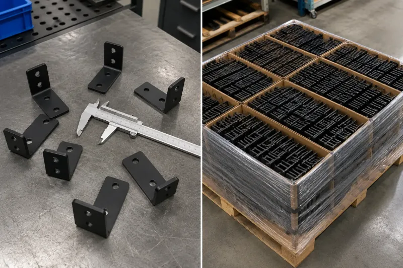
The same bracket design manufactured at different scales: a small prototype batch for fit and function verification (left) versus a full production run with organized packaging for delivery (right).
How SR-MFG Manufactures Brackets
SR-MFG provides complete sheet metal bracket manufacturing services. From laser cutting and CNC bending to welding, hardware pressing, surface treatment, and dimensional inspection, we can support the full process.
Before production begins, our engineering team conducts a manufacturability review for every drawing received, identifying potential issues such as hole-to-bend conflicts, overly tight tolerances, and missing specifications. This upfront review can prevent unexpected problems during production and help customers optimize their designs for both cost and quality.
We support bracket orders from single-piece prototypes to mass production of thousands of parts. The process selection is tailored according to your quantity and timeline.
For more information or to request a quotation, please send your drawing files in STEP, IGES, DXF, or PDF format, together with the material, thickness, quantity, surface treatment, and delivery requirements to our engineering team.