You have designed a formed sheet metal bracket. The prototype passes inspection, the geometry is finalized, and now the production drawing needs a heat treatment callout.
You open the standards and realize there is no single symbol that says “make this part harder.” The callout has to be written out — and it has to be written out correctly, because vague or incomplete heat treatment notes are one of the most common reasons drawings get sent back before production even starts.
This guide walks through exactly what goes into a heat treatment callout on a sheet metal drawing, where to place it, which processes apply to sheet metal parts, and how to avoid the mistakes that cause rework.
Where Heat Treatment Callouts Belong on a Drawing
Heat treatment information does not belong in a single fixed location. Where you place it depends on how the information needs to be read — by the fabricator, the heat treater, and the quality inspector.
There are three standard placement options:
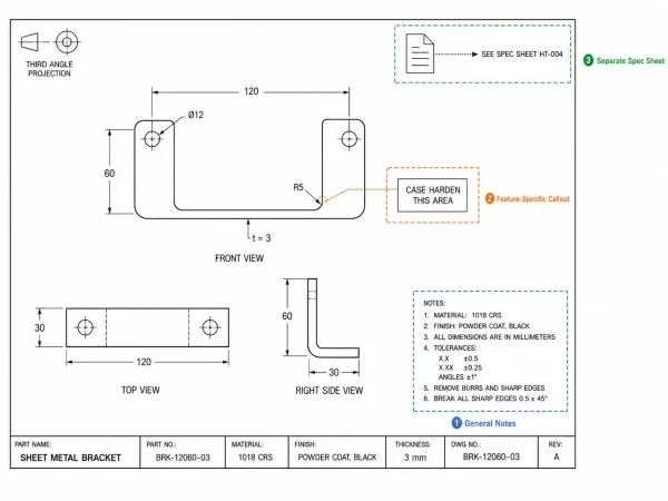
A clean technical illustration showing an engineering drawing layout with three labeled zones — general notes block, feature-specific leader line callout, and reference to a separate specification sheet — indicating where heat treatment information is placed.
General Notes block. This is the most common location for process-level heat treatment requirements that apply to the entire part. On a technical drawing, a note such as “STRESS RELIEVE PER AMS 2759” in the title block or notes area tells every downstream reader that the part requires a specific thermal process.
Feature-specific callout. When heat treatment applies to a specific area — for example, case hardening only on the teeth of a gear or the wear surface of a bracket — a leader line or flag note attached to that feature provides clearer instruction than a general note.
Separate specification sheet. For parts with complex or multi-step heat treatment sequences (anneal, then harden, then temper), a dedicated process specification sheet referenced in the drawing notes keeps the drawing clean and the requirements unambiguous.
If you are unsure which approach to use, the general rule is: one simple process goes in the notes; area-specific treatment gets a feature callout; multi-step sequences go on a separate sheet.
The Five Elements Every Heat Treatment Callout Must Include
A heat treatment callout is not a single line. It is a set of linked information, and leaving out any one element creates room for misinterpretation.
Here are the five items that must appear — either directly in the callout or by reference to a standard.
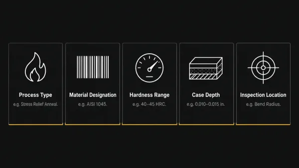
A horizontal infographic with five labeled sections — Process Type, Material Designation, Hardness Range, Case Depth, and Inspection Location — each shown as an icon with a brief example text, arranged in a clean left-to-right layout.
Element 1: Process Type
State the specific heat treatment process.
Do not write “heat treat” or “harden” — those terms are too broad and force the heat treater to guess your intent.
Common process designations include stress relief annealing, full annealing, through hardening, case hardening (carburizing or carbonitriding), and precipitation hardening.
Each process produces a different microstructure and mechanical result, so the drawing must specify which one is required.
Element 2: Material Designation Using Standard Codes
The sheet metal material specification on the drawing must use the correct standard designation — not a trade name or a generic material description.
Write “AISI 1045” instead of “medium carbon steel.”
Write “SAE 4140” instead of “chrome-moly alloy.”
Heat treaters rely on the exact alloy code to set furnace temperatures, soak times, and quench media. An incorrect or vague material reference can result in an entire batch being processed to the wrong specification.
Element 3: Hardness Value and Range
Specify hardness as a range, not a single value.
A callout of “40–45 HRC” is realistic and achievable; “42 HRC” is not, because hardness varies across a part due to differences in section thickness, edge proximity, and material heat lot.
Also specify the correct hardness scale.
Rockwell C (HRC) is standard for hardened steels; Rockwell B (HRB) for annealed or soft materials; Brinell (HB) for larger components.
Mixing scales without a conversion note is a frequent source of rejection — hardness conversions are approximate, and compounding approximations introduces error.
Element 4: Case Depth (When Applicable)
For case-hardened parts — those that are carburized or carbonitrided — the callout must distinguish between effective case depth (measured from the surface to a specific hardness level, typically 50 HRC) and total case depth (the full distance carbon has diffused into the part).
Specify which one you mean, and give a range.
For example:
“Effective case depth 0.007–0.012 in. at 50 HRC.”
A single case depth value, like a single hardness value, leaves too much room for interpretation.
Element 5: Inspection Location
The drawing must indicate where hardness testing should be performed.
Heat treatment alters the surface and core of a part differently, and hardness readings taken at the wrong location can falsely indicate that the process failed.
For a formed bracket, the critical inspection point might be the bend radius; for a wear surface, it might be the functional contact area.
Mark the inspection point on the drawing with a leader note or reference it in the general notes.
Common Heat Treatment Processes for Sheet Metal and How to Call Them Out
Sheet metal parts typically undergo a narrower range of heat treatment processes than heavy machined components. The following four are the most common.
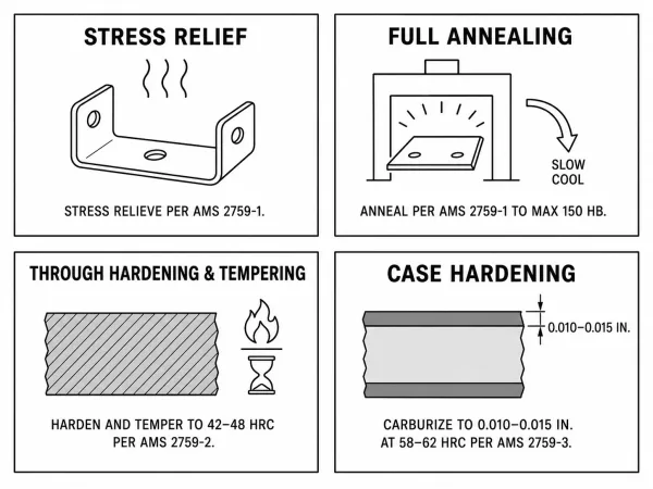
A four-panel grid showing simplified visual representations of stress relief annealing, full annealing, through hardening and tempering, and case hardening, each panel including the process name and a typical drawing callout example.
Stress relief annealing
This is the most frequently specified post-forming treatment for sheet metal.
Stress relief can reduce residual stresses introduced during sheet metal bending, stamping, or welding without significantly changing the material’s hardness or strength.
Typical callout:
“STRESS RELIEVE PER AMS 2759-1, METHOD X.”
Full annealing
Used when the part needs maximum ductility — for example, a component that will undergo further forming operations after the initial cut.
Full annealing heats the material above its upper critical temperature and slow-cools it.
Typical callout:
“ANNEAL PER AMS 2759-1 TO MAX 150 HB.”
Through hardening and tempering
For sheet metal parts that require high hardness across the full cross-section — springs, wear plates, cutting blades.
The callout must specify both the hardening and tempering steps, because tempering is what controls the final hardness.
Typical callout:
“HARDEN AND TEMPER TO 42–48 HRC PER AMS 2759-2.”
Case hardening (carburizing or carbonitriding)
Less common on thin sheet metal because the case-to-core ratio can be unfavorable on thin sections, but used on thicker sheet or plate components that need a hard surface with a tough core.
Typical callout:
“CARBURIZE TO EFFECTIVE CASE DEPTH 0.010–0.015 IN. AT 58–62 HRC PER AMS 2759-3.”
Sheet Metal–Specific Concerns: Distortion, Tolerances, and Post-Form Heat Treatment
Heat treatment on sheet metal is not the same as heat treatment on a 50 mm steel block.
Thin sections heat and cool quickly, warp more easily, and respond differently to quenching.
These factors directly affect what you write on the drawing.
Distortion is the primary risk.
A flat sheet metal part that is through-hardened will almost certainly distort. The thinner the part, the greater the distortion.
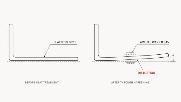
A technical illustration showing a flat sheet metal bracket on the left in its pre-heat-treatment state with flatness tolerance noted, and on the right the same bracket after through hardening with visible warpage and a callout indicating the distortion measurement.
If the application requires tight flatness tolerances after heat treatment, the drawing must call out the flatness requirement as a post-heat-treatment measurement — not just as a forming tolerance.
Otherwise, the part may pass forming inspection but fail after hardening.
Stress relief after forming reduces downstream problems.
Specifying stress relief annealing before any final machining or critical dimension verification is a standard practice for formed sheet metal parts.
On the drawing, place the stress relief note before the final tolerance callout in the process sequence so the fabricator knows the order of operations.
Dimensional compensation may be needed.
Heat treatment can cause predictable dimensional changes, including small amounts of growth or shrinkage, depending on the process and the specific sheet metal materials being treated.
For precision assemblies, the sheet metal design should define critical final dimensions as post-heat-treatment requirements and account for any predictable thermal movement during forming and processing.
This is uncommon on simple sheet metal brackets but critical on parts that interface with mating components.
Common Mistakes That Cause Rework — and How to Avoid Them
The most expensive heat treatment problems are not caused by the heat treater. They are caused by unclear drawings.
Here are the five mistakes fabricators see most often.
Writing “heat treat to spec” without specifying which spec.
There are dozens of heat treatment standards, and each one covers different processes, materials, and acceptance criteria.
“Heat treat per spec” means nothing unless the spec number is named.
Specifying a single hardness value instead of a range.
Hardness is not uniform across a part.
A single value like “45 HRC” is either unachievable in some areas or too loose in others.
Always specify a range that accounts for the part’s geometry and material.

A split comparison showing two engineering drawing callouts side by side — the left side labeled “Incorrect” shows a single hardness value “45 HRC,” and the right side labeled “Correct” shows a hardness range “42–48 HRC,” with a brief annotation explaining why a range is required.
Using trade names instead of standard designations.
“Stainless 304” is acceptable in conversation but not on a production drawing.
The correct callout is “ASTM A240 Type 304” or the equivalent standard for your region and application.
Trade names can refer to different compositions across suppliers.
Omitting inspection locations.
If the drawing does not say where to test hardness, the heat treater will test wherever is convenient — which may not be the critical functional area.
This leads to parts that pass hardness testing but fail in service.
Mixing hardness scales without explanation.
If the drawing specifies “40 HRC” in one note and “380 HB” in another, the reader has to convert — and hardness conversions are approximate.
Specify one scale throughout, or if multiple scales are unavoidable, note the conversion basis (e.g., “per ASTM E140”).
Quick Checklist Before You Send That Drawing
Before releasing a production drawing with a heat treatment callout, verify these items:
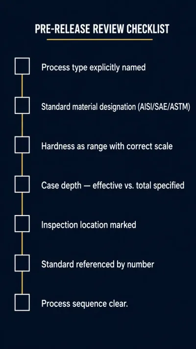
A clean checklist-style infographic showing seven review items that should be verified before releasing a drawing with a heat treatment callout, each item accompanied by a simple checkmark or checkbox graphic.
- Process type is explicitly named (not “heat treat” or “harden”)
- Material uses a standard designation (AISI, SAE, ASTM — not a trade name)
- Hardness is specified as a range with the correct scale (HRC, HRB, or HB)
- Case depth specifies effective vs. total and includes a range (if applicable)
- Inspection location is marked on the drawing
- The applicable standard is referenced by number (AMS 2759, SAE J411, etc.)
- Process sequence is clear if multiple treatments are required
Five minutes of review at the drawing stage can save five days of back-and-forth between engineering and the shop floor.