
You annotate four blind rivets on the assembly drawing — “4x RIVET, BLIND, 3/16″ dia” — and release the file. Two days later, the fabricator’s email asks five questions: What grip range? Which head style? What mandrel material? Installed from which side? What should final inspection check? Nothing on your drawing answers them.
A rivet callout is the set of notes that tells a shop which fastener to buy, how to install it, and how to accept the finished joint. When the callout is complete, quoting, procurement, and inspection run without a second conversation. This guide explains why a diameter alone is not a specification, how callout requirements change with rivet type, and which fields belong on the drawing before you release it.
Why “RIVET + Diameter” Is Not a Specification
A line like “RIVET, 3/16″ dia” names a fastener family and a nominal size. It leaves three decisions to the fabricator: what to buy, how to install the joint, and how to verify it after installation.
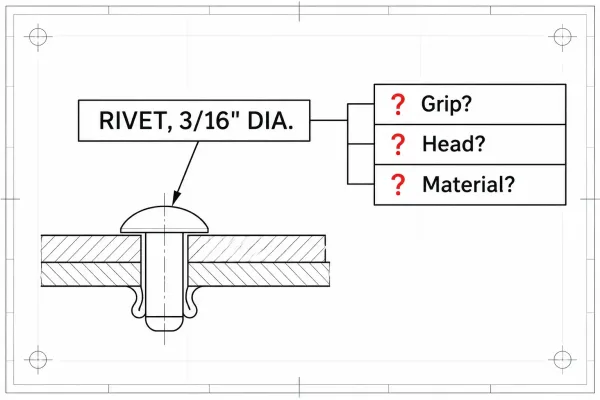
A rivet note with only diameter leaves grip, head style, and material unspecified.
Each decision carries real cost. Procurement cannot order from a diameter alone, because grip range — the combined thickness of sheets the rivet is built to join — determines which catalog part actually fits the stack. Installation depends on head style and install side, and a silent drawing invites the shop to assume values that may not match your assembly. Inspection has no pass or fail basis without acceptance criteria such as head seating or protrusion limits, so the fabricator either applies internal defaults or stops to ask.
That is why vague rivet notes generate clarification emails instead of parts. The drawing is the contract for the joint; anything it does not say becomes an assumption somewhere downstream.
Callout Priorities Change with Rivet Type
Not every fastener labeled “rivet” needs the same information. The three families common in sheet metal assemblies — blind rivets, solid rivets, and rivet nuts — each have fields that must be exact, while the rest can follow shop standards.
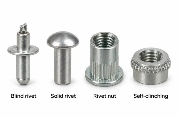
The four fastener families covered in this guide, shown side by side.
Blind Rivets: Grip Range and Mandrel Material Dominate
Blind rivets are installed from one side: a mandrel — the stem pulled through the rivet body to form the second head — snaps off after setting. This is the default fastener for enclosures and brackets, and its callout stands or falls on two fields. Grip range defines the sheet-stack window the rivet can clamp (for example, 2.0–3.5 mm); outside that window the joint is loose or the rivet cannot be set at all. Mandrel material should be stated when the assembly sees vibration or corrosive exposure, since a steel mandrel in an aluminum body is common but not universal.
Solid Rivets: Head Style and Length Become Critical
Solid rivets are driven and bucked with pressure from both sides, mostly in structural or legacy work. Head style and driven length must be explicit, because head forms and protrusion heights are not interchangeable across standards. If the drawing uses an aerospace-style rivet symbol system, the symbol legend has to travel with the file — those conventions are not self-explanatory in a general sheet metal shop.
Rivet Nuts: Thread, Sheet Range, and Install Side
Rivet nuts are threaded inserts installed into a punched hole, giving thin sheet a reusable threaded point. Specify thread size, body style, and the sheet thickness range the insert grips. Mark the install face as well: the insert flange seats on one side, and a mirrored installation turns finished parts into rework.
Boundary Note: Self-Clinching Fasteners Are Not Rivets
Self-clinching fasteners are pressed into a hole so the host sheet flows into an undercut groove. They are sometimes grouped with rivets in a BOM, but their callout follows catalog part-number practice, not rivet practice. Keep the notes separate.
What a Complete Callout Contains
The table below lists the fields a complete rivet callout covers, with example values and what the shop does when a field is missing.
| Field | Example callout text | If omitted |
|---|---|---|
| Type | BLIND RIVET | Shop selects a family or asks |
| Diameter | 3/16 in (4.8 mm) body | Hole size guessed from stock |
| Grip range | 2.0–3.5 mm grip | Wrong catalog part ordered |
| Head style | Dome / countersunk / large flange | Dome assumed; flush faces fail |
| Material | Al body, steel mandrel | Mixed-metal corrosion risk |
| Install side | Install from exterior face | Joint built mirrored |
| Acceptance | Head fully seated, no gap | No inspection basis |
Grip Range Comes from the Stack, Not the Nominal Thickness
Grip range is the total thickness the rivet must clamp: all sheets plus any interlayer such as a gasket or a plated buildup. Do not derive it from nominal sheet thickness alone. A stack of two 1.5 mm panels is 3.0 mm bare, but a powder-coated surface can add 0.05–0.15 mm per side before assembly, which pushes the joint outside a tight grip window. State grip as a range unless the stack is fully controlled.
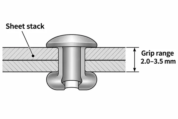
Grip range is the sheet-stack window the rivet body must clamp.
Head Style, Material, and Finish
Dome heads are the working default. Countersunk heads need a countersink callout on the hole — otherwise the shop must decide whether to add a second operation. Large-flange heads spread load on soft or thin sheets. Material follows the joined sheets for galvanic compatibility, and finish (as-received, painted over, plated) should be stated when appearance or corrosion resistance is part of acceptance.
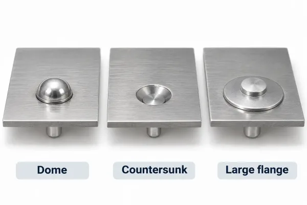
Three common rivet head styles and how they sit on the sheet surface.
Drawing Note vs. BOM vs. RFQ
Each field has one home, and duplicating it invites version drift. Per-joint installation data — type, grip, quantity, install side, acceptance — belongs in the drawing note. A chosen catalog part number and its quantity belong in the BOM. Commercial assumptions, including customer-supplied hardware, belong in the RFQ or PO.
Spacing, Edge Distance, and Hole Size: What to Annotate and What to Leave
What the Shop Applies When the Drawing Is Silent
When spacing is not dimensioned, the shop applies its internal standard: edge distance from rivet center to sheet edge of about 2× rivet diameter, center-to-center pitch of about 3× diameter, and hole size roughly rivet diameter plus 0.1–0.25 mm for clearance. These defaults keep holes off the bend radius and away from weak edges. They are workable — but they are the shop’s judgment, not yours.
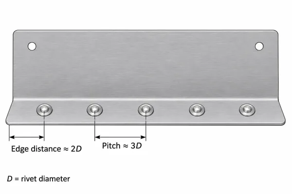
Standard shop defaults for rivet pitch and edge distance.
When Explicit Values Matter
Dimension spacing and edge distance when the joint carries structural load, when the rivet pattern is visible on a cosmetic face, or when the edge margin is inherently tight (narrow flanges, features close to a bend). In these cases a default layout can produce a weak or ugly joint, and the fix after production is scrap or rework.
What Incomplete Callouts Cost — and the Pre-Release Check
An incomplete note costs time and money in four predictable ways. Clarification rounds add two to five days per cycle, and each question sits in an inbox while the quote or schedule slips. Quotes built on assumed standard hardware get re-quoted when a non-standard rivet is named later. A wrong grip range produces loose joints or a batch that cannot be set at all. A flipped install side turns finished parts into rework.
Before releasing a drawing, check each joint against this list:
- Fastener type named (blind, solid, or rivet nut)
- Diameter matches the hole callout
- Grip range covers the full stack, including finishes
- Head style stated where clearance or appearance matters
- Body and mandrel materials stated where corrosion matters
- Install face marked on the assembly
- Acceptance criteria written (seating, protrusion, or an inspection reference)
A callout is complete when the shop can procure, install, and inspect the joint without asking a question. If any of those three jobs still needs an email, the note is not finished.
FAQs