
A coating thickness callout looks like a finishing detail — one number next to a color. Then the first assembly build arrives. The press fit will not start. The sliding cover binds. The threaded inserts that seated cleanly on the bare-metal prototype now fight the film in every hole. The coating did exactly what the spec asked. The spec never asked how much room the film would take.
Coating thickness is one of the few finish specifications that acts as a mechanical variable. Get it right and the part stays protected, looks as intended, and still goes together.
What Coating Thickness Actually Measures
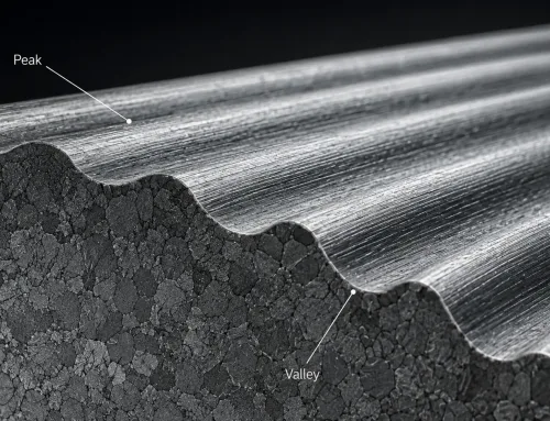
Coating thickness — often written as dry film thickness or DFT — is the depth of the cured coating layer, measured from the substrate surface to the outer face of the film. On fabricated sheet metal parts, the cured film is what matters: it is the layer that remains after solvents evaporate (liquid paint) or after powder melts, flows, and crosslinks in the cure oven.
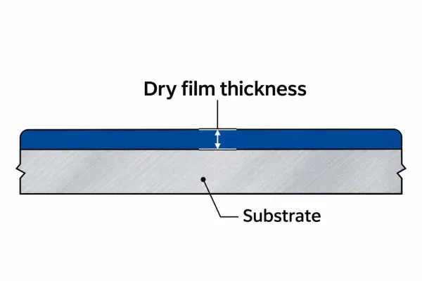
Cross-section of a coated sheet metal surface — dry film thickness runs from the substrate face to the outer surface of the cured coating.
Dry Film vs. Wet Film
Wet film thickness is read while the coating is still liquid. It includes carrier solvents or unmelted material that disappear during cure, so a wet film reading is always larger than the dry film that survives. Application crews use wet film gauges to tune spray parameters; buyers and inspectors accept parts on dry film, because that is the layer that protects the part and occupies space in the assembly.
Units Engineers Use: Micron and Mil
Two units show up in real specifications. A micron (µm) is one-thousandth of a millimeter. A mil is one-thousandth of an inch (0.001 in), equal to 25.4 µm. Metric drawings typically call out microns; US drawings often use mils. Mixing them without conversion is a reliable way to end up with a film 25 times too thick.
Typical Film-Build Ranges for Powder Coating and Paint
Most sheet metal coating work falls into two families. The ranges below are typical for steel and aluminum fabrication, not absolute limits:
| Coating | Typical dry film (µm) | Typical dry film (mils) | Where it shows up |
|---|---|---|---|
| Powder coating (polyester / epoxy) | 50–100 | 2–4 | Enclosures, brackets, panels |
| Heavy-duty powder build | 100–150 | 4–6 | Outdoor or aggressive chemical exposure |
| Liquid paint — single coat | 25–50 | 1–2 | Primers, light industrial finishes |
| Liquid paint — primer + topcoat | 50–100 | 2–4 | Multi-coat equipment finishes |
Powder coating on sheet metal is usually specified at 60–80 µm for general enclosures. Below about 50 µm the film becomes hard to hold uniformly and edge coverage drops sharply. Above about 100–120 µm, appearance and dimensional effects start to dominate. Liquid paint builds thinner per coat but is normally applied as a system, so the total film lands in a comparable range.
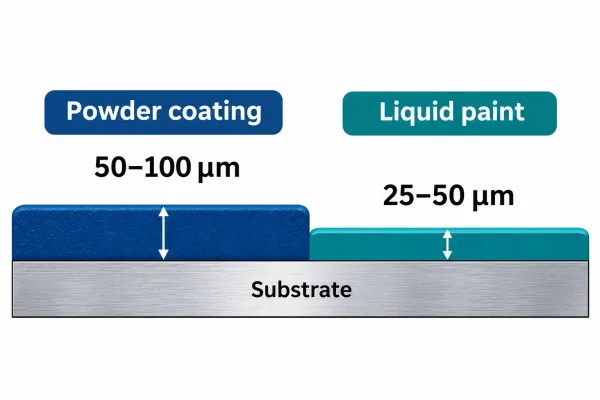
Typical dry film builds side by side — powder coating 50–100 µm against liquid paint 25–50 µm per coat.
Protection: How Thin Is Too Thin and How Thick Is Too Thick
Protective performance rises with film thickness only up to a point. The useful target is a window: a minimum that guarantees barrier coverage, and a maximum that avoids the penalties of over-build.
Below the Minimum: Pinholes and Edge Exposure
Under-thickness shows up as pinholes (microscopic voids through the film), low-build edges, and early corrosion creep from scratches. A 40 µm film on powder-coated steel can pass a visual check and still fail in service, because coverage is discontinuous at exactly the features that corrode first.
Above the Maximum: Cracking and Diminishing Returns
Over-thickness buys little extra barrier performance. It does buy internal stress: thick films crack more readily at formed edges and embossments, and they can crack again during assembly. Heavy builds also bury surface geometry and can telegraph substrate defects instead of hiding them.
Where Thickness Fails First: Edges, Bends, and Welds
Sharp edges, tight bend radii, and weld beads are the classic low-build zones. Powder and paint both thin out over sharp geometry, so the corrosion life of a coated part is usually set by its edges and welds — not by the flat panels where thickness is easiest to measure. A minimum specified on the flat surface does not guarantee coverage where it is needed most.
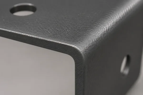
Film thins at sharp edges and bend radii — the zones where coated parts corrode first.
What Film Build Does to Appearance
Appearance is not a separate topic from thickness. For most visible finishes, an acceptable look exists only inside a narrow band of film build.
Texture and Surface Geometry
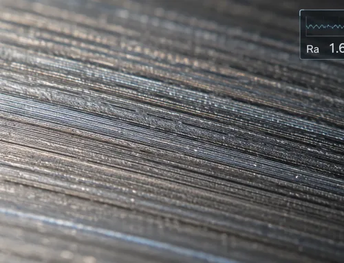
Too little film and substrate texture, laser striations, or weld discoloration stay visible. Too much and the surface develops orange peel (a rippled texture from film flow), edges round off, and fine features — logo recesses, louvers, crisp break lines — soften. Wrinkle and texture powders are especially sensitive: their pattern develops within a defined build window and flattens outside it.
Consistency Across Features and Batches
Coating thickness varies across a single part. Recesses receive less film than faces, and hardware masks small areas that differ from the surrounding surface. Across a batch, rack position and oven loading shift the build by several microns. For appearance-critical parts, state thickness as a range with defined measurement points, because “same color” without a build range is not a repeatable requirement.
How Coating Film Enters the Dimensional Stack
Here is where a finish specification becomes a mechanical one. Cured film is deposited on every coated surface, and it occupies real space.
Per-Side Build and the Clearance Budget
Coating adds thickness on each side of a feature. A 75 µm film on both walls of a slot removes 150 µm of clearance. On a Ø8.00 mm hole, 80 µm per side reduces the effective diameter to roughly 7.84 mm — a change larger than a standard H8 fit tolerance. Any dimension that mates, slides, seals, or threads is a coated dimension.
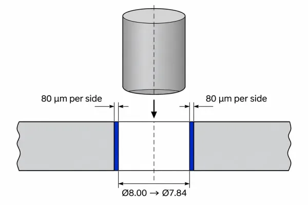
Film builds on every coated surface — 80 µm per side reduces a Ø8.00 mm hole to about Ø7.84 mm.
Features at Risk: Press Fits, Holes, Threads, Sliding Surfaces
Press fits and bearing bores bind when the allowance ignores film. Sheet-metal threads lose class and engagement, and many fabricators mask threaded holes rather than compensate. Self-clinching fasteners installed after coating can crack a thick film; installed before coating, their installation zone will not receive full coverage. Sliding covers, rails, and door edges need uniform build, or they gall at the high spots.
How Much Allowance to Leave
A workable rule: if a fit or clearance is tighter than about 0.2 mm (8 mils) total, state the coating allowance explicitly on the drawing rather than leaving it to the fabricator’s default. Either oversize the mating features to recover the film, mask the functional surfaces, or select a thinner finish. Unspecified tight fits are the most common reason coated prototypes fail at assembly.
Measuring and Accepting the Specified Range
Thickness is verified on the cured part, after forming and welding, because those operations change geometry at edges and corners where the film is thinnest.
Methods in Brief
Non-destructive gauges cover most sheet metal work. Magnetic induction measures non-magnetic coatings on steel; eddy current measures non-conductive coatings on aluminum and other non-ferrous substrates. Ultrasonic gauges handle multi-layer systems. Destructive cross-section microscopy remains the referee method when a dispute reaches the microscope.
Where and How Many Points
Acceptance should not rest on a single reading. A practical plan measures flat faces, at least one edge, and a representative recess on several parts per lot. Published practice (SSPC-PA 2 for paint systems, ASTM D7091 for gauge operation) defines reading counts and result classification — reference the standard in the quality section instead of inventing numbers in a meeting.
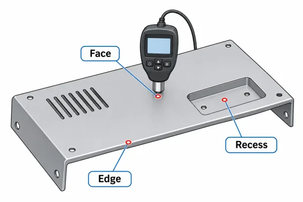
Acceptance reads flat faces, at least one edge, and a recess — not a single spot on the panel.
Accept the Range, Not a Single Number
Film thickness is process output, not a setpoint. A specification that reads “80 µm” invites an argument at 78 µm. A range — for example, 60–100 µm — is measurable, quotable, and realistic. State the minimum, the maximum, the measurement locations, and the lot sampling rule. A reading inside the range is a pass; a reading outside it becomes a defined nonconformance instead of a debate.
How to Specify It on Drawings and RFQs
The Elements a Callout Needs
An executable coating callout answers five things:
- Coating type — powder or liquid paint
- Dry film thickness as a range — minimum and maximum
- Measurement locations — which features are judged
- Areas excluded from coating — threads, grounding faces, mating surfaces
- Color and appearance class — gloss level, texture, reference sample if needed
Naming the inspection standard in the same note closes the loop.
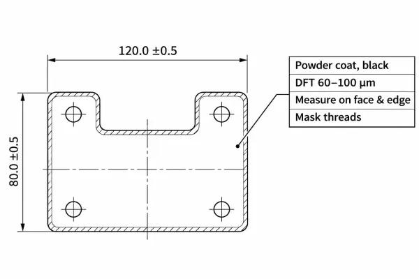
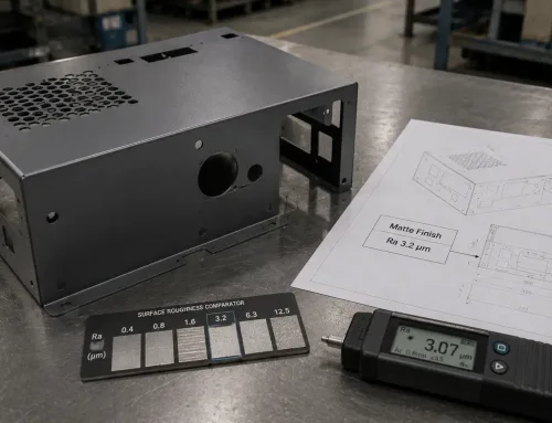
A complete callout states coating type, dry film range, color, and areas excluded from coating.
What “Powder Coat, Black” Leaves Unresolved
A one-line finish note forces the fabricator to assume a build. Typical assumptions — 60–80 µm powder everywhere, threads masked, no allowance in fit dimensions — solve some problems and create others, and they are rarely the assumptions you would have written down. Once the quote returns “as quoted,” the drawing can no longer settle a thickness dispute.
If a fit is tight or an appearance class matters, have the coating allowance reviewed with the fabricator before release. It is a short conversation that replaces a long rework cycle.
Key Takeaways
- Coating thickness is the cured dry film on the substrate, quoted in microns or mils (1 mil = 25.4 µm).
- Powder on sheet metal usually runs 50–100 µm (2–4 mils); liquid paint systems land in a comparable total range.
- Protection sets the minimum; appearance and fit set the maximum. Edges, bends, and welds fail first.
- Every coated mating dimension loses about twice the film thickness in clearance — budget it, mask it, or oversize it.
- Specify a range with measurement locations, not a single number, and confirm tight fits with your fabricator before release.
FAQs