A production workflow is the ordered sequence of stages that a part passes through—from initial design review to finished delivery.
In sheet metal fabrication, this workflow is more than a list of manufacturing steps. It is the interplay of material movement, quality checkpoints, and information exchange between the buyer and the fabricator at every stage.
Understanding how a production workflow operates helps engineers and procurement teams set realistic expectations, prepare complete RFQ packages, and avoid the delays that come from incomplete information or missed handoffs.
Why It Matters for Buyers and Engineers
When a buyer submits a drawing for quotation, the fabrication workflow that follows is shaped by what that drawing contains—and what it leaves out.
A clearly dimensioned part with specified material grade, surface finish, and tolerance requirements moves through the workflow with fewer interruptions. A drawing that omits these details triggers back-and-forth clarification, which adds days to the lead time before production even begins.
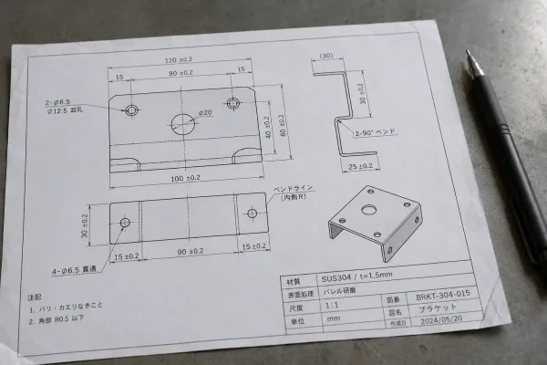
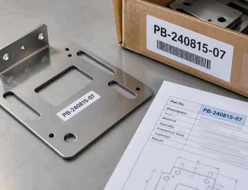
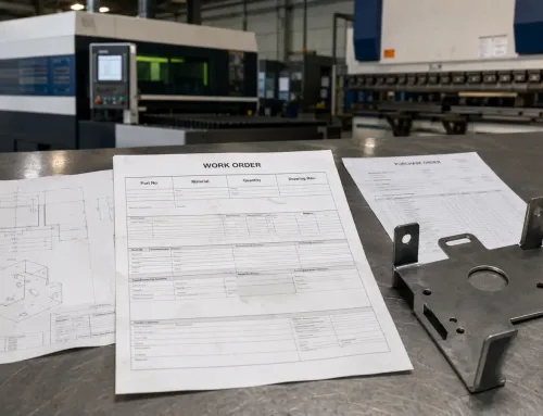
A complete engineering drawing with clear dimensioning, tolerance callouts, and material specification reduces back-and-forth communication during the production workflow.
For engineers, understanding the production workflow means knowing where your design decisions have the most impact.
The bend radius you specify affects whether the part can be formed on standard tooling or requires a custom die. The tolerance you call out determines how many parts will pass inspection on the first run.
These are not abstract choices—they directly influence how smoothly the workflow proceeds.
For procurement teams, the workflow provides a framework for evaluating suppliers.
A fabricator that runs a structured workflow with defined inspection points is more likely to deliver consistent parts on schedule than one that moves jobs through the shop on instinct.
A Typical Production Workflow in Sheet Metal Fabrication
The exact sequence varies with part complexity, but most sheet metal orders follow a recognizable path through the shop.
Here is how a typical order moves from inquiry to shipment at a custom sheet metal fabrication provider like SR-MFG.
Drawing Review and DFM Analysis.
Before any material is ordered, the engineering team reviews the customer’s drawings and 3D models.
This stage checks for manufacturability: Are bend radii achievable with standard tooling? Do hole positions conflict with bend lines? Are tolerances tighter than process capability allows?
Design-for-manufacturability (DFM) feedback is returned to the buyer at this point, and production does not proceed until both sides agree on the final design.
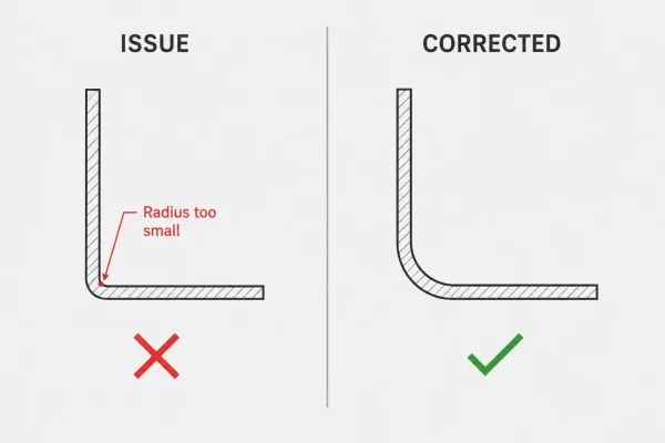
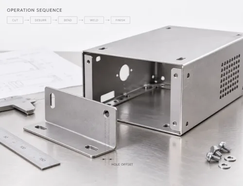
DFM analysis identifies issues like unachievable bend radii before production begins, allowing the buyer and fabricator to agree on a corrected design.
Material Sourcing.
Once the design is approved, the required sheet stock is procured.
Material sourcing time depends on whether the specified alloy and thickness are standard inventory items or require mill orders.
Common grades such as SPCC cold-rolled steel, SUS304 stainless steel, or AL5052 aluminum are typically available within days. Specialty alloys or non-standard thicknesses may take weeks.
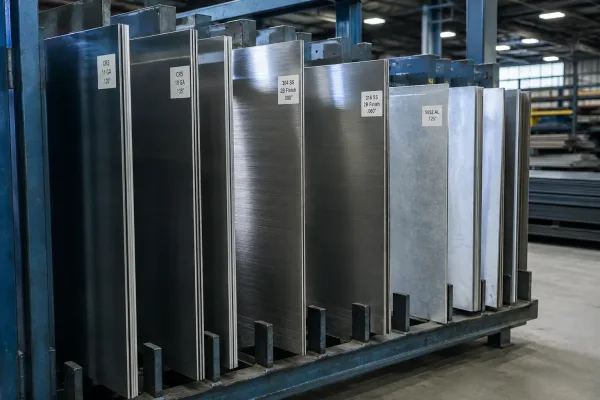
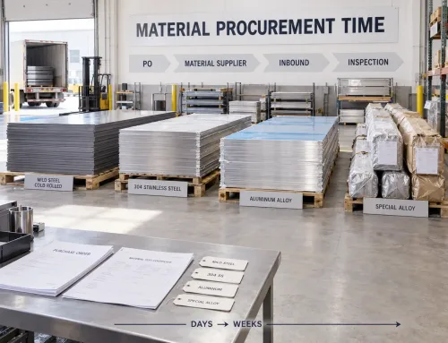
Common sheet metal alloys such as SPCC, SUS304, and AL5052 are typically held in stock, while specialty materials may require extended mill order lead times.
Cutting.
Flat sheets are cut to the required blank shape using laser cutting, punching, or shearing.
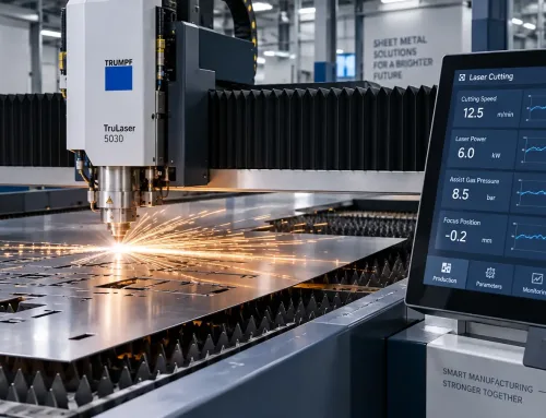
Laser cutting is the most common method for custom parts because it handles complex contours without dedicated tooling and holds tight dimensional tolerances—typically within ±0.1 mm.
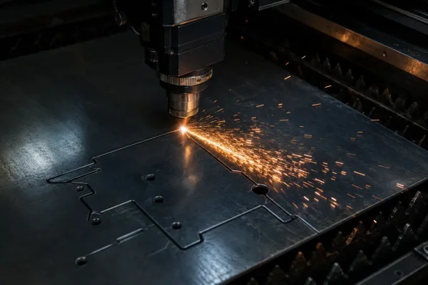
Laser cutting is the most common blanking method for custom sheet metal parts, capable of holding dimensional tolerances within ±0.1 mm.
Bending and Forming.
Cut blanks are formed on press brakes to create the final three-dimensional geometry.
Each bend requires a specific punch-and-die combination, and the sequence in which bends are made matters—certain features must be formed before others to avoid tooling interference.
This is where design decisions made in CAD have their most direct physical consequence.
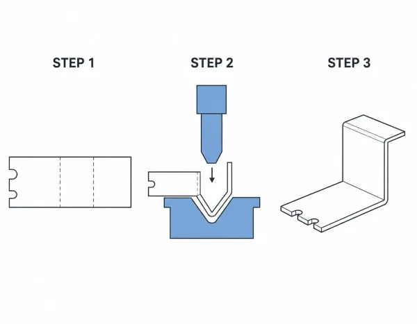
Three-step bending sequence diagram showing a flat blank progressing through press brake forming to produce a finished L-bracket
Welding and Assembly.
If the design calls for multiple components to be joined, the parts move to welding or mechanical assembly.
Spot welding, TIG welding, MIG welding, rivet insertion, and hardware insertion (PEM fasteners such as self-clinching nuts and studs) are common methods.
The choice depends on the material, required strength, and cosmetic requirements.
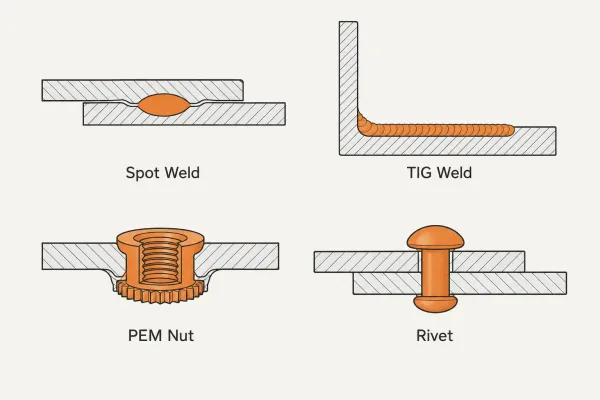
The joining method is selected based on material type, required strength, and cosmetic requirements of the final assembly.
Surface Treatment.
After forming and assembly, parts receive their specified finish.
Powder coating is the most common finish for sheet metal enclosures and brackets, offering good corrosion resistance and a consistent appearance. Anodizing is typical for aluminum parts.
Plating (zinc, nickel, or chrome) is used when specific conductivity, wear resistance, or cosmetic requirements apply.
Each surface treatment adds cycle time and introduces its own quality criteria.
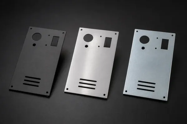
Powder coating, anodizing, and plating each add distinct surface properties — the right finish depends on the part’s corrosion resistance, conductivity, and cosmetic needs.
Quality Inspection.
Throughout the workflow—and especially at this stage—parts are measured against the drawing specifications.
Dimensional checks, surface finish verification, weld integrity assessment, and visual inspection are performed.
For orders with formal quality requirements, a First Article Inspection (FAI) report may be generated before bulk production proceeds.
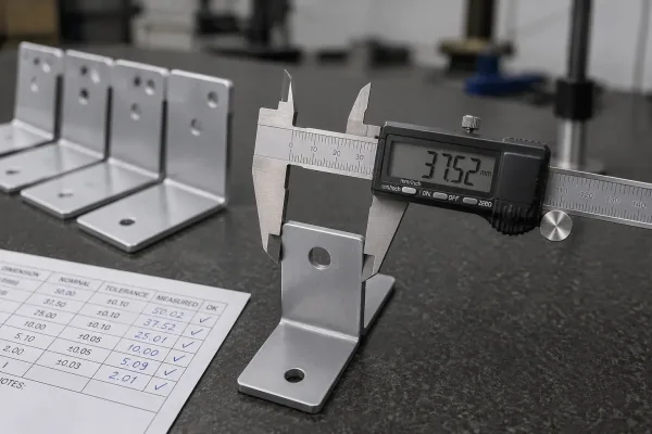
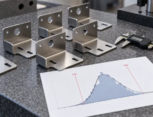
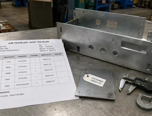
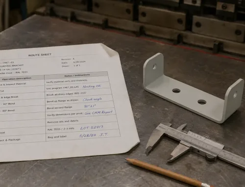
Dimensional checks using calibrated instruments verify that formed parts meet the drawing specifications before they proceed to the next stage.
Packaging and Shipment.
Parts that pass inspection are cleaned, packaged according to the buyer’s requirements (or standard protective packaging if none are specified), and shipped.
For international orders, export documentation, customs declarations, and shipping method selection are part of this final stage.
Quality Control Checkpoints at Each Stage
A production workflow without defined inspection points is a workflow that will discover problems late—usually at final inspection, when rework is most expensive.
Structured quality control is built into the workflow at several key moments:
| Stage | Checkpoint | What Is Verified |
|---|---|---|
| Material Receiving | Incoming Quality Control (IQC) | Material certificate matches order spec; sheet thickness within tolerance; surface condition acceptable |
| After Cutting | First Piece Inspection | Cut dimensions match drawing; edge quality (burr, dross) within acceptable limits |
| After Bending | In-Process Check | Bend angles and flange lengths measured; no cracking or deformation at bend lines |
| After Welding | Weld Inspection | Weld strength, appearance, and penetration meet requirements; no porosity or undercut |
| After Surface Treatment | Coating Verification | Film thickness, adhesion, color consistency, and coverage meet specification |
| Before Shipment | Outgoing Quality Control (OQC) | Final dimensional check; visual inspection; packaging integrity |
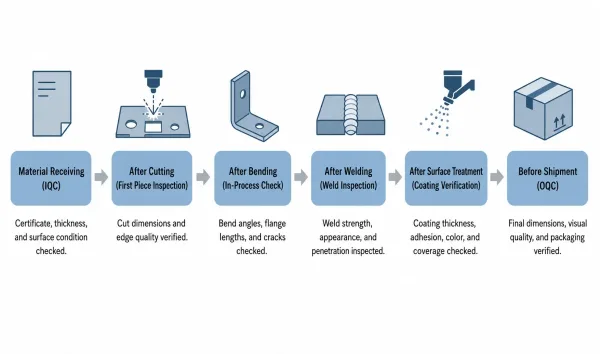
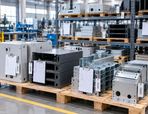
Quality checkpoints are built into the workflow at each major stage so that defects are caught where they are cheapest to correct.
These checkpoints are not bureaucratic overhead.
They are the mechanism by which problems are caught at the stage where they are cheapest to fix—a mis-cut blank is scrap material, but a mis-cut blank that reaches welding is scrap material plus wasted labor.
How Buyer Input Shapes the Workflow
The buyer’s role in the production workflow begins long before parts arrive at the loading dock.
The information provided at the RFQ stage sets the trajectory for everything that follows.
A complete sheet metal RFQ package typically includes::
- 2D drawings with full dimensioning and tolerancing (GD&T preferred)
- 3D CAD files (STEP or IGES format) for programming and DFM analysis
- Material specification — not just the alloy name, but the standard, temper, and thickness
- Surface finish requirements — type, color, thickness, and standard (e.g., ASTM B117 salt spray hours)
- Quality requirements — inspection level, sampling plan, First Article Inspection if required
- Packaging and labeling requirements
- Target delivery date and quantity
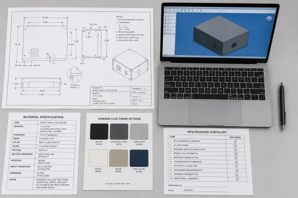
A complete RFQ package — including drawings, 3D models, material specs, finish requirements, and quality criteria — enables the fabricator to quote accurately and plan production without interruption.
When these items are provided upfront, the fabricator can generate an accurate quote, plan material procurement, and schedule production without interruption.
When they are missing, each gap becomes a question that must be answered before the workflow can advance—and each question adds time.
The most common source of workflow disruption, in practice, is not a machine failure or a material shortage.
It is an unanswered question about what the buyer actually needs.
Common Workflow Disruptions and How to Prevent Them
Production workflows rarely follow a perfectly linear path.
Here are the most common disruptions and what buyers and fabricators can do to prevent them:
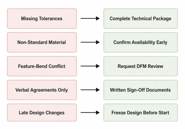
Five common sheet metal production workflow disruptions paired with their corresponding prevention methods in a side-by-side comparison layout
Incomplete drawing information.
Missing tolerances, unspecified surface finish requirements, or ambiguous material grades force the fabricator to pause and request clarification.
Prevention: provide a complete technical package at the RFQ stage, and designate a single point of contact for technical questions.
Material procurement delays.
Non-standard alloys, unusual thicknesses, or small order quantities may require mill orders with lead times of several weeks.
Prevention: specify standard, readily available materials whenever possible, and confirm material availability before committing to a delivery date.
Rework due to design issues.
Features placed too close to bend lines, hole diameters that conflict with hardware insertion, or tolerances that exceed process capability result in parts that do not meet specification.
Prevention: request a DFM review before production begins, and be open to design adjustments that improve manufacturability without compromising function.
Communication gaps between design and production.
When the engineering team that designed the part and the production team that builds it are not aligned, assumptions fill the gaps—usually incorrectly.
Prevention: use documented communication (written DFM feedback, signed-off drawings, formal change orders) rather than verbal agreements.
Late design changes.
A design change made after material has been cut or bending has begun can scrap work in progress and reset the workflow to an earlier stage.
Prevention: freeze the design before production starts, and manage any subsequent changes through a formal revision process with clear impact assessment.