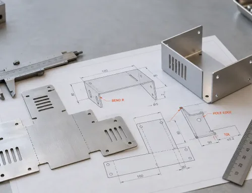
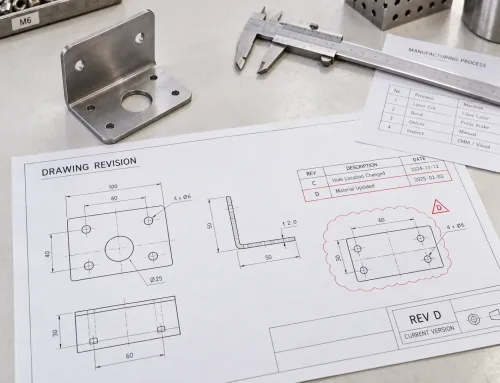
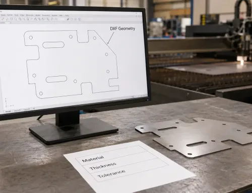
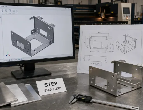
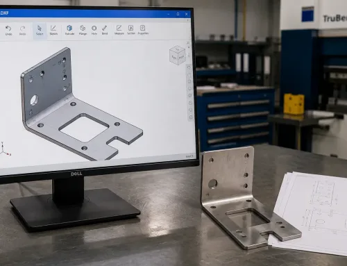
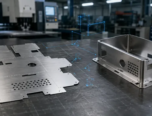
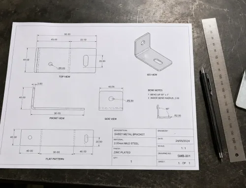
Most people think a 2D drawing is just a 3D model flattened onto paper — a couple of views, some dimensions, done.
In general-purpose machining, that assumption might hold up. In sheet metal fabrication, it gets your drawing sent back with a list of questions.
A 2D drawing in manufacturing is not a simplified version of a 3D file. It is the document that tells the manufacturer what the 3D model cannot:
- which tolerances matter
- how the part should be bent
- where the welds go
- what happens at the edges
For sheet metal parts specifically, a 2D drawing carries information that no STEP or IGES file can communicate on its own.
What a 2D Drawing Actually Is
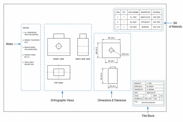
Annotated layout diagram showing the standard zones of a 2D engineering drawing including title block, orthographic views, dimensions, notes, and bill of materials
A 2D drawing — sometimes called an engineering drawing, technical drawing, or manufacturing drawing — is a standardized, annotated representation of a part on a flat surface.
It communicates geometry, dimensions, tolerances, materials, surface finishes, and manufacturing instructions through a system of views, symbols, and notes that follow established standards like ASME Y14.5 or ISO 128.
What Makes It Different from a 3D Model
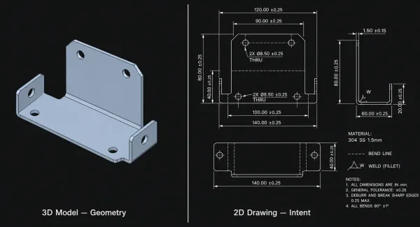
This comparison illustrates how a 3D model defines the part’s shape while a 2D drawing communicates the tolerances, materials, and manufacturing instructions that the 3D file alone cannot convey.
A 3D CAD file defines the shape of a part. A 2D drawing defines the quality.
The STEP file tells the manufacturer what the part looks like; the drawing tells them what the part needs to be.
This distinction matters because designing sheet metal for real-world manufacturing means accounting for material behavior, tooling limits, and physics — none of which exist in a mathematically perfect 3D model.
A hole that looks identical to ten other holes in CAD might be the only press-fit bearing seat on the actual part. Without the drawing specifying that, the manufacturer treats all eleven holes the same.
The Core Elements of a 2D Drawing
A factory-ready 2D drawing is built from several standardized components.
Each one carries a specific purpose, and leaving any of them incomplete creates ambiguity that flows directly into quoting, production, and inspection.
Title Block
The title block sits in the bottom-right corner and functions as the administrative header of the drawing.
It contains the:
- part name
- drawing number
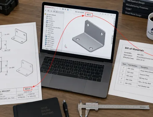
- revision level
- material specification
- general tolerances
- scale
- name or approval stamp of the engineer who released it
For sheet metal parts, the material callout here — for example, “304 Stainless Steel, 1.5 mm” — is the first thing a manufacturer checks before quoting.
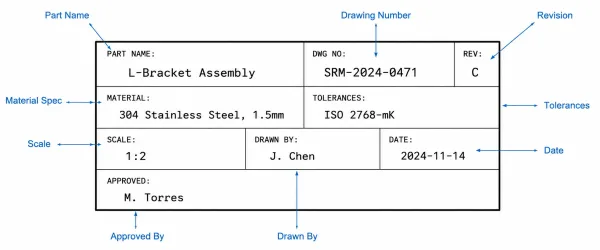
This annotated title block shows the key fields a manufacturer reads first, including part name, drawing number, revision level, material specification, and general tolerances.
Orthographic Views
Most engineering drawings use orthographic projection to show the part from multiple flat angles: typically a front view, a top view, and a right-side view.
These views eliminate perspective distortion and give the manufacturer measurable geometry.
In the United States, third-angle projection is standard; in Europe and most of Asia, first-angle projection is more common. The projection symbol in the title block removes any guesswork.
Dimensions and Tolerances
Dimensions define the size and location of every feature. Tolerances define how much variation is acceptable.
Without explicit tolerance callouts, manufacturers default to general tolerances — usually ISO 2768 for linear dimensions — which may or may not match what your assembly requires.
Critical fits, mating surfaces, and hole positions need individual tolerance annotations on the drawing.
Material and Finish Specifications
Beyond the material callout in the title block, the drawing should specify surface treatments and finishes where they apply.
“Powder coat, RAL 9005, 60–80 μm” is actionable. “Paint black” is not.
The more specific the callout, the less back-and-forth during production.
Notes and Special Instructions
The notes section covers everything that does not fit neatly into a dimension or symbol:
- deburring requirements
- sharp edge break radii
- cleaning instructions
- packaging preferences
- reference to a separate specification document
For sheet metal parts, notes often carry critical information about bend sequence, weld inspection criteria, or masking areas.
Why 3D Models Alone Are Not Enough
A 3D model is necessary for modern manufacturing — it drives CNC programming, nesting software, and automated quality inspection.
But it is not sufficient.
The reason is straightforward: a 3D model carries geometry, not intent.
It does not tell the manufacturer which hole is a clearance hole and which is a tapped hole with a Class 2B fit.
It does not specify that a surface must be free of scratches because it is a visible cosmetic face.
It does not indicate that a bend radius must be held to ±0.5° because the part mates with an injection-molded housing.
A 2D drawing captures design intent. It turns geometry into manufacturing instructions.
When a manufacturer receives both a STEP file and a drawing, the STEP file drives the machine — but the drawing drives the decisions.
What a 2D Drawing Must Include for Sheet Metal Parts
Sheet metal fabrication introduces a set of requirements that generic 2D drawing guides rarely mention.
These are not optional add-ons — they are the difference between a drawing that gets quoted in hours and one that generates a week of email chains.
Bend Lines, Bend Direction, and Bend Tables
Every bent feature needs a callout showing the:
- bend line location
- bend angle
- inside radius
- bend direction
The bend direction should be shown as up or down relative to the datum.
A bend table — listing each bend’s angle, radius, and sequence — eliminates ambiguity on parts with multiple bends.
Without this information, the press brake operator is guessing, and guesses on the brake lead to scrapped parts.
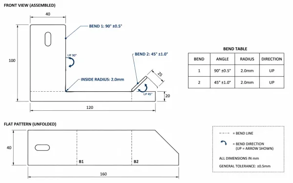
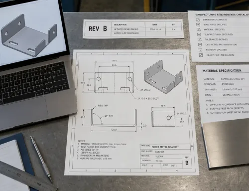
2D engineering drawing of a sheet metal bracket showing bend line locations, bend angles, inside radii, bend direction arrows, and an accompanying bend table
Flat Pattern / Unfolded View
For any part that will be laser-cut or punched from flat stock and then bent, the drawing should include a flat pattern view showing the part in its unfolded state.
This view is what the cutting operator uses to program the machine.
It should show the:
- overall blank dimensions
- hole positions relative to the flat edge
- bend line locations projected onto the flat surface
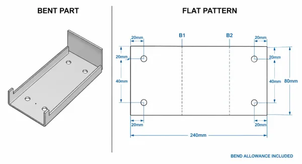
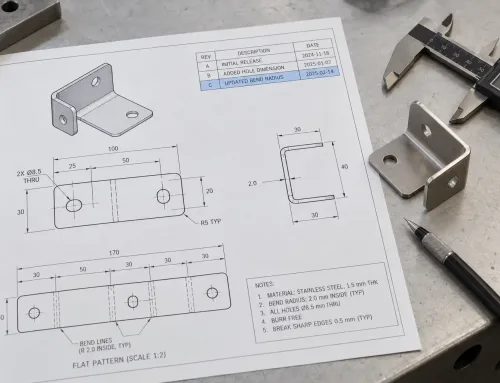
This illustration compares a bent sheet metal part with its flat pattern view, showing how bend lines, hole positions, and blank dimensions appear in the unfolded state used for laser cutting.
Weld Symbols and Joint Types
If the part involves welding, the drawing must use standard weld symbols — per AWS A2.4 or ISO 2553 — to define the sheet metal welding requirements, including:
- joint type
- weld size
- weld length
- weld location
A note saying “weld all joints” is not enough.
It leaves the welder to decide fillet size, penetration depth, and whether the weld is continuous or intermittent.
Those decisions affect strength, distortion, and cost.
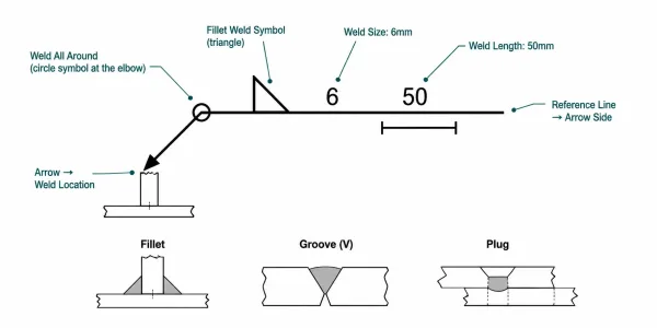
This diagram breaks down a standard weld symbol into its components — reference line, arrow, weld type, size, and length — and shows three common joint types used in sheet metal fabrication.
Burr Direction and Grain Direction
Laser cutting leaves a burr on one side of the cut — typically the bottom.
When a part has a visible cosmetic face, the drawing should indicate which side should be burr-free or specify the acceptable burr height.
Similarly, for parts that will be bent, the grain direction of the sheet stock matters.
Bending parallel to the grain line increases the risk of cracking, especially in aluminum and stainless steel.
Sheet Metal-Specific Tolerances
Beyond standard linear tolerances, sheet metal parts need callouts for:
- bend angle tolerance — typically ±0.5° to ±1°
- flatness across the finished part
- positional tolerance for holes near bend lines
Holes near bend lines can distort when the material deforms during bending.
These are not covered by general ISO 2768 tolerances and must be specified individually.
How a Manufacturer Reads Your Drawing
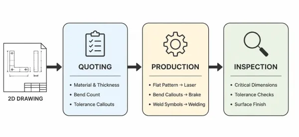
This flowchart shows the three stages — quoting, production, and inspection — where a manufacturer reads a 2D drawing, and what specific information is extracted at each stage.
When a drawing arrives at a sheet metal fabrication shop, it passes through three stages — and each stage reads the drawing differently.
Quoting
The estimator scans the title block for material and thickness, counts the number of bends, identifies any welding or secondary operations, and checks for tolerance callouts that might require special tooling or additional inspection steps.
Missing information means the estimator either delays the quote to ask questions, or makes assumptions.
Assumptions in quoting lead to surprises in invoicing.
Production
The manufacturing engineer uses the drawing to plan the process sequence:
cut first, then bend, then weld, then finish.
The flat pattern goes to the laser or punch programmer.
Bend callouts go to the press brake setup sheet.
Weld symbols go to the welding station.
If any of this information is missing or unclear, production stops — or worse, continues with the wrong interpretation.
Inspection
Quality control uses the drawing to define inspection and acceptance criteria.
Every critical dimension, tolerance, and surface finish on the drawing becomes a checkpoint.
Features that are not dimensioned are assumed to be non-critical and are not inspected.
If a feature matters but is not on the drawing, it will not be caught until the part fails in assembly — which is the most expensive place to find a problem.
When a Drawing Goes Wrong
The cost of an incomplete or ambiguous drawing is rarely visible on the drawing itself.
It shows up downstream — in:
- quoting delays
- production rework
- parts that pass inspection but fail in assembly
A common scenario: a designer submits a 3D model with no 2D drawing, or with a drawing that omits bend tolerances.
The manufacturer quotes based on standard tolerances, produces the part, and delivers it.
The customer assembles the part and finds that flanges do not align because the bend angles drifted ±1° — which was within the manufacturer’s default tolerance but outside the assembly requirement.
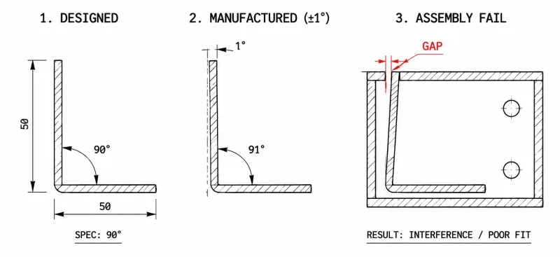
This illustration shows how a 1° bend angle deviation — within the manufacturer’s default tolerance — creates a visible gap when the sheet metal part is assembled with its mating housing, causing a fit failure.
The result is a batch of parts that meet the drawing but do not work.
Another frequent issue is material specification.
A drawing that says “aluminum” without specifying alloy and temper — 5052-H32 versus 6061-T6, for example — leaves the manufacturer to choose based on cost or availability.
The two alloys behave very differently during bending:
- 5052 is forgiving
- 6061 is prone to cracking at tight radii
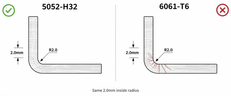
This cross-section comparison shows how 5052-H32 aluminum bends cleanly at a 2mm radius while 6061-T6 develops inside radius cracks under the same conditions, highlighting the importance of material specification on drawings.
The wrong choice means scrapped parts and a redrawn specification.
These problems are not caused by bad design.
They are caused by drawings that do not carry enough information to protect the designer’s intent through the manufacturing process.
FAQs
SR-MFG provides sheet metal fabrication services including laser cutting, bending, welding, and finishing. If you have a design ready for review, upload your drawing for a manufacturing assessment.