Most people treat an inspection plan as a form the quality department fills out after production is done.
In sheet metal fabrication, that assumption is the source of a surprising number of rework orders, delayed shipments, and frustrated emails between buyers and suppliers.
An inspection plan is not a bureaucratic checkbox.
It is a written agreement — between the designer, the buyer, and the manufacturer — on exactly what will be checked, how it will be measured, and what counts as acceptable.
When that agreement is missing or vague, parts get made to one standard and judged against another.
The disagreement usually surfaces at the worst possible moment: after the first batch is already cut, bent, and coated.
What an Inspection Plan Actually Is
An inspection plan is a document that defines the inspection activities required to verify that a manufactured part meets its design specifications.
It answers five questions for every feature that matters: what to inspect, how to inspect it, how often, who is responsible, and what the acceptance criteria are.
In practice, the plan translates drawing callouts and engineering requirements into a sequence of measurable checkpoints.
A dimension marked ±0.1 mm on a drawing means nothing on the shop floor until someone specifies which tool to use, when to measure, and what to do if the reading is out of range.
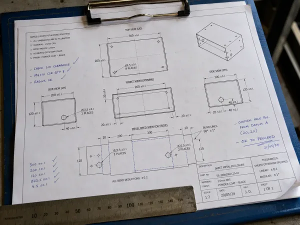
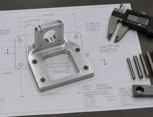
A sheet metal engineering drawing with dimensional callouts, showing how design specifications are translated into measurable inspection checkpoints.
The inspection plan provides that translation.
The document sits within a broader quality system but has a distinct role.
It is not a general process control strategy — it is focused specifically on verification and acceptance.
Its audience includes QC technicians, production supervisors, and, critically, the buyer or engineer who needs to confirm that the agreed-upon requirements are being met.
What Goes Into an Inspection Plan
A complete inspection plan for sheet metal parts typically covers six elements.
Each one answers a different question about the inspection process:
- Inspection items — Which features or characteristics will be checked. For a sheet metal enclosure, this might include overall dimensions, hole positions, bend angles, surface finish, and hardware installation.
- Acceptance criteria — The specific values or ranges that define a passing result. For example, a hole diameter of 6.0 mm ±0.1 mm, or a bend angle of 90° ±1°.
- Inspection method — The tool or technique used to measure. A digital caliper for linear dimensions, a go/no-go gauge for hole diameter, a surface roughness tester for finish quality, or visual inspection for cosmetic defects.
- Sampling frequency — How many parts are checked and when. First-article inspection typically requires 100% dimensional check on one to three parts. Production runs may use AQL-based sampling (Acceptance Quality Limit) or statistical process control.
- Responsible party — Who performs and verifies the inspection. This could be an in-house QC operator, a third-party inspector, or the buyer’s own receiving inspection team.
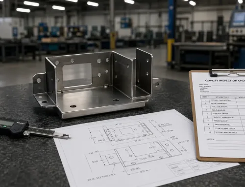
- Records — What documentation is generated. Inspection reports, measurement data sheets, photographs of critical features, and certificates of conformance all fall into this category.
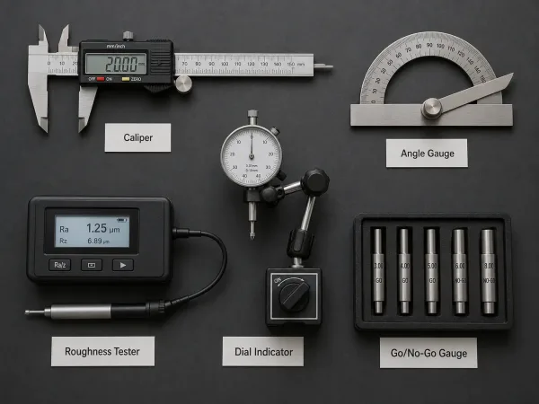
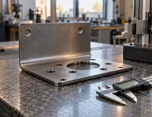
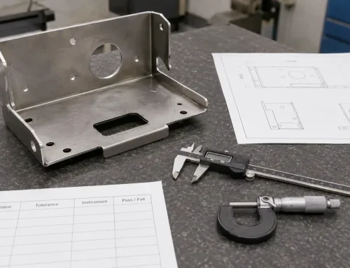
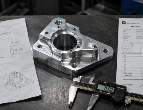
Common inspection tools used in sheet metal quality control: digital calipers for linear dimensions, angle gauges for bend verification, surface roughness testers for finish quality, and go/no-go gauges for hole diameter checks.
The level of detail depends on the part’s complexity and the buyer’s requirements.
A simple sheet metal bracket may need a one-page plan covering five dimensions.
A multi-bend aerospace enclosure with inserted hardware and powder coating may require a multi-page document with process-specific checkpoints.
Inspection Plan vs. Control Plan vs. ITP
These three terms are often used interchangeably, but they describe different levels of documentation in a quality system.
| Document | What It Is | Scope | Common Standards | Typical Use |
|---|---|---|---|---|
| Control Plan | A high-level document describing all process controls for a product or process | Covers the entire manufacturing process — inputs, outputs, parameters, and controls | IATF 16949, AIAG guidelines | Automotive, high-volume manufacturing |
| Inspection Plan | A focused document defining inspection and acceptance criteria for specific characteristics | Subset of the control plan — deals only with verification and measurement | ISO 9001, customer-specific requirements | General manufacturing, sheet metal fabrication |
| Inspection and Test Plan (ITP) | A project-level document defining inspection and test hold/witness points for stakeholders | Broader than an inspection plan — includes approval gates, third-party witnessing, and documentation requirements | Contract-specific, ASME, AWS, construction codes | Construction, welding, piping, heavy fabrication |
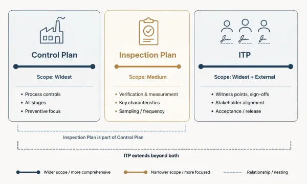
A comparison diagram illustrating how a Control Plan, Inspection Plan, and Inspection and Test Plan (ITP) differ in scope — from broad process control down to focused verification and stakeholder sign-off.
A control plan is the master document.
An inspection plan extracts the verification activities from that control plan and specifies them in actionable detail.
An ITP adds a layer of stakeholder involvement — it defines not just what to check, but who needs to witness, approve, or sign off at each stage.
For most sheet metal fabrication orders, a well-written inspection plan is sufficient.
An ITP becomes necessary when third-party inspection, customer witness points, or regulatory requirements are involved — common in aerospace (AS9100D), medical devices, or defense contracts.
What a Sheet Metal Inspection Plan Actually Checks
Generic inspection plan definitions tell you to “check critical dimensions.”
In sheet metal fabrication, the act
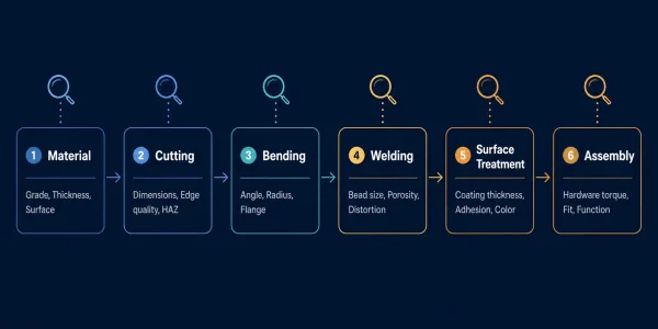
A stage-by-stage inspection map for sheet metal fabrication, showing what is checked at each production phase — from incoming material through cutting, bending, welding, surface treatment, and final assembly.
Here is what a typical plan covers, organized by production phase:
Incoming Material
- Material grade and specification (e.g., 304 stainless steel per ASTM A240)
- Sheet thickness — measured at multiple points to verify uniformity
- Surface condition — visible rust, scratches, or contamination
Cutting — Laser, Waterjet, Punch
- Overall part dimensions — length, width, profile accuracy
- Feature positions — hole locations, slot positions, cutout dimensions
- Edge quality — burr height, dross, heat-affected zone (HAZ) width
- Kerf width and cut surface roughness
Bending
- Bend angle — measured with a protractor or angle gauge
- Inside bend radius — compared against the 4T rule or drawing specification
- Flange length — the distance from the bend line to the edge
- Dimensional accumulation — overall part dimensions after multiple bends
Welding
- Weld appearance — bead width, uniformity, surface defects
- Weld size — throat thickness, leg length per AWS D1.3 or drawing callout
- Defects — porosity, undercut, cracking, incomplete fusion
- Distortion — warping or bowing caused by heat input
Surface Treatment
- Coating thickness — powder coat or paint film measured per ISO 2360 or ASTM D7091
- Adhesion — cross-hatch test per ASTM D3359
- Color consistency — visual comparison to approved sample or RAL/Pantone reference
- Coverage — uniform application, no bare spots or runs
Assembly and Hardware
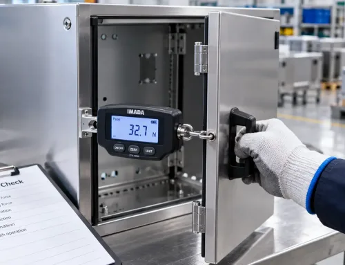
- Inserted hardware — PEM nuts, standoffs, rivets: torque values, flush condition, pull-out strength
- Assembly fit — gap between mating parts, alignment of mounting holes
- Functional testing — door operation, gasket seating, connector alignment (where applicable)
Not every part requires inspection at every stage.
The plan should reflect the actual operations performed on the part and flag the characteristics that are critical to function or fit.
Sample Stage vs. Production Stage: Two Different Plans
A common misconception is that the inspection plan used during first-article inspection (FAI) is simply a stricter version of the production inspection plan.
In reality, the two stages have fundamentally different purposes, and the inspection plans should reflect that.
First-Article Inspection (FAI)
- Purpose: Verify that the manufacturing process can produce a conforming part from scratch
- Scope: 100% dimensional inspection of all drawing callouts, typically on 1–3 parts
- Documentation: Complete measurement data for every feature, material certifications, process records
- Trigger: New part, design revision, process change, new supplier, or production restart after a gap
Production Inspection
- Purpose: Confirm that the process remains stable and critical characteristics stay within tolerance
- Scope: Focused on critical-to-function (CTF) and critical-to-quality (CTQ) dimensions, not every callout
- Documentation: Sampling-based records, SPC charts where applicable, non-conformance logs
- Trigger: Ongoing production runs, typically governed by AQL sampling plans or process capability data
The key distinction is breadth versus consistency.
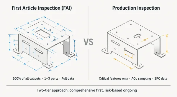
A side-by-side visual comparing first-article inspection (FAI) — which checks all dimensions broadly — against production inspection, which focuses narrowly on critical-to-function characteristics using sampling methods.
FAI is broad — it checks everything because the goal is to validate the process.
Production inspection is narrow and repeatable — it monitors the features most likely to drift because the goal is to catch problems before they reach the buyer.
A buyer who insists on FAI-level inspection for every production part will drive up cost and lead time without a proportional quality benefit.
A buyer who applies no inspection plan beyond FAI risks discovering dimensional drift only when parts fail at assembly.
The right approach is a two-tier plan: comprehensive for the first article, risk-based for production.
When and How to Use an Inspection Plan as a Buyer
The most effective time to define an inspection plan is before the first RFQ is sent — not after the first sample arrives and fails to fit.
When a buyer submits a drawing without inspection criteria, the manufacturer makes assumptions.
They will apply their default tolerances (usually ISO 2768-mK for linear dimensions, ±1° for bend angles), use their standard surface finish spec, and inspect only what their internal process requires.
If the buyer’s actual requirements are tighter or different, the disagreement surfaces during first-article approval — often after tooling, setup, and material have already been committed.
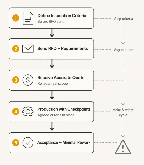
A buyer-side workflow showing the recommended sequence: define inspection criteria at the RFQ stage, receive an accurate quote, execute production with agreed checkpoints, and complete final acceptance with minimal back-and-forth.
An inspection plan sent with the RFQ accomplishes three things:
- It tells the manufacturer what matters. Not every dimension on a drawing is equally critical. Highlighting the five or ten features that truly affect fit, function, or appearance allows the manufacturer to focus their process control where it counts.
- It makes the quote more accurate. Tighter tolerances, additional inspections, and third-party witnessing all add cost. When these requirements are visible upfront, the quote reflects the real scope of work rather than a best-case assumption.
- It reduces back-and-forth after production. A clear acceptance benchmark means fewer debates about whether a part “passes” or not. The criteria were agreed before the first chip was cut.
A practical starting point for buyers: include a brief inspection requirements table in the RFQ package.
It does not need to be a formal document — even a simple table listing critical dimensions, their tolerances, and any special inspection requests (coating thickness, hardware pull-out test, cosmetic surface standard) gives the manufacturer a clear basis for planning and quoting.