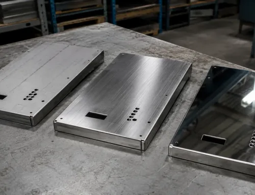
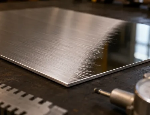
Every manufactured surface has a texture. Under magnification, what looks smooth to the naked eye reveals a landscape of peaks and valleys shaped by the manufacturing process. Surface roughness is the engineering term for that microscopic topography — and it directly affects how a part performs in assembly, under load, and over its service life.
This glossary entry explains what surface roughness means, which parameters engineers use to define it, how to read surface finish callouts on drawings, and what roughness values to expect from common manufacturing processes.
What Is Surface Roughness?
Surface roughness is a measure of the fine, closely spaced irregularities on a machined or fabricated surface. These irregularities — peaks and valleys with spacings typically below 1 mm — are left by the cutting tool, laser beam, grinding wheel, or other material removal process.
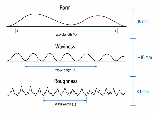
The three components of surface texture: roughness (short wavelength), waviness (medium wavelength), and form (long wavelength).
Engineers distinguish roughness from two other components of surface texture:
- Waviness refers to broader, more widely spaced undulations caused by machine vibration, workpiece deflection, or thermal distortion. Waviness has a longer wavelength than roughness, typically in the 1–10 mm range.
- Form is the overall macroscopic shape of the part — flatness, cylindricity, or other geometric tolerances. Form deviations operate at the longest wavelength.
Together, roughness, waviness, and form make up the complete surface profile. When a drawing includes a surface finish requirement, it is almost always referring to the roughness component.
Why Surface Roughness Matters
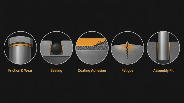
Five functional areas where surface roughness directly affects part performance: friction, sealing, coating adhesion, fatigue life, and assembly fit.
Surface roughness is not a cosmetic specification. It influences how a part interacts with other components and with its operating environment:
- Friction and wear. A rougher surface generates more friction between mating parts, accelerating wear. Bearing journals and sliding surfaces typically require Ra values below 0.8 µm.
- Sealing performance. Gasket faces and O-ring grooves depend on a controlled surface finish to maintain a leak-tight seal. Too rough, and the seal leaks; too smooth, and the seal can stick or wear prematurely.
- Coating and plating adhesion. Paint, powder coating on sheet metal parts, and electroplating all depend on controlled surface conditions for reliable adhesion. A surface that is too smooth may cause coating delamination.
- Fatigue resistance. Surface peaks act as stress concentrators. In fatigue-critical components, a smoother finish can significantly extend service life.
- Assembly fit. Press fits and interference fits are sensitive to roughness — surface peaks are compressed during assembly, effectively changing the interference dimension.
Surface Roughness Parameters: Ra, Rz, Rq, Rt, and Rsk
Several parameters exist to describe surface roughness numerically. Each captures a different aspect of the surface profile.
Ra — The Most Common Parameter
Ra (arithmetic average roughness) is the arithmetic mean of the absolute deviations of the profile from the mean line over a specified evaluation length. It is the parameter specified on the vast majority of engineering drawings worldwide, expressed in micrometers (µm) or microinches (µin).
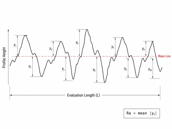
Ra is the arithmetic mean of absolute deviations from the mean line across the evaluation length.
A surface with Ra 1.6 µm has, on average, 1.6 µm of deviation from the mean line. However, Ra tells you nothing about the shape of the profile — whether the surface is dominated by sharp peaks, deep valleys, or uniform waves.
Rz — What Ra Misses
Rz is the average of the maximum peak-to-valley heights within five consecutive sampling lengths. Because it captures the extreme height of the profile rather than the average, Rz is more sensitive to isolated scratches, deep valleys, or sharp peaks that Ra would average out.
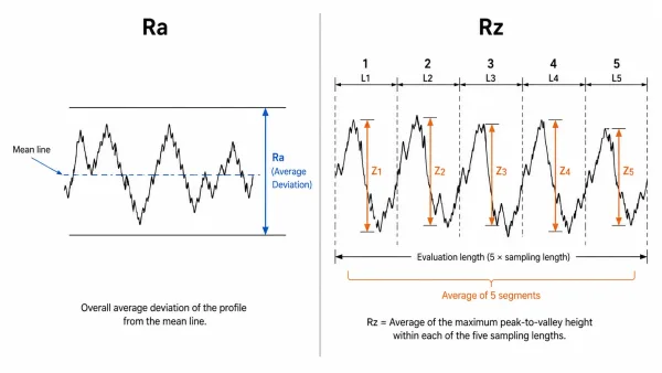
Ra measures the average deviation across the profile; Rz measures the average peak-to-valley height within each sampling length.
Rz is commonly specified alongside Ra on sealing surfaces, fatigue-critical parts, and surfaces where a single deep scratch could cause failure.
Rq (RMS) — When You Need Statistical Sensitivity
Rq (root mean square roughness) is the root mean square average of profile deviations. Because it squares each deviation before averaging, Rq gives more weight to extreme peaks and valleys than Ra does.
Rq is preferred in optical surface engineering, statistical process control, and research applications where sensitivity to outliers matters.
Rt — Worst-Case Peak-to-Valley
Rt is the total height of the profile — the vertical distance between the highest peak and the lowest valley over the entire evaluation length. It is a single worst-case number.
Rt is useful for screening for defects (a deep scratch, a machining burr) that would be invisible in an Ra value but could compromise coating thickness or create a leak path.
Rsk — Peak vs. Valley Dominance
Rsk (skewness) describes the asymmetry of the roughness profile. A positive Rsk means the surface is dominated by peaks (plateau-like); a negative Rsk means it is dominated by valleys (porous or porous-like).
Rsk matters for bearing surfaces (negative Rsk retains lubricant), paint adhesion (positive Rsk provides mechanical keying), and seal faces. Two surfaces with identical Ra values can have very different Rsk — and very different functional performance.
How to Read Surface Finish Callouts on Engineering Drawings
The µin Shorthand
On many engineering drawings — particularly those following ASME Y14.36 — you will see surface finish values written as plain numbers without units: “125,” “32,” “16,” “8.” These are Ra values in microinches (µin).
Common conversions:
| Shorthand | Ra (µin) | Ra (µm) | ISO Grade (N) |
|---|---|---|---|
| 125 | 125 | 3.2 | N8 |
| 63 | 63 | 1.6 | N7 |
| 32 | 32 | 0.8 | N6 |
| 16 | 16 | 0.4 | N5 |
| 8 | 8 | 0.2 | N4 |
If a drawing calls out “32,” it means Ra 32 µin, which is Ra 0.8 µm — a finish typically achieved by precision grinding or fine turning.
ISO 1302 Symbol System
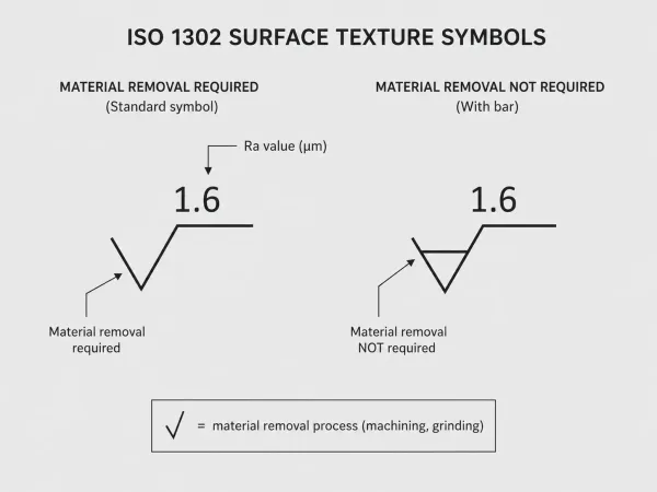
ISO 1302 surface texture symbols: the checkmark symbol indicates material removal required; a number above the line specifies the Ra value in µm.
ISO 1302 defines a symbol system for surface texture requirements on technical drawings. The basic symbol is a checkmark (√). Additional markings indicate:
- √ — Material removal required (the surface is produced by a material removal process such as machining or grinding).
- √ with a horizontal bar — Material removal not required (the surface is produced by a process that does not remove material, such as casting or forging).
- A number placed above the line specifies the Ra value in µm.
When no symbol or value is shown, the surface is assumed to be produced “as-is” by the manufacturing process, with no specific roughness requirement.
Typical Surface Roughness by Manufacturing Process
Different manufacturing processes leave characteristic surface roughness ranges. The following table provides typical Ra values for common processes:
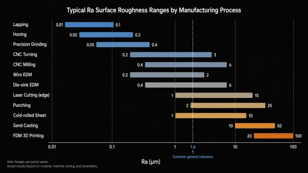
Typical surface roughness (Ra) ranges achievable by common manufacturing processes, from ultra-smooth lapping to rough FDM 3D printing.
Sheet Metal Processes
| Process | Typical Ra (µm) | Notes |
|---|---|---|
| Laser cutting (edge) | 3.2–12.5 | Roughness varies with gas type, speed, and material thickness |
| Punching (inner wall) | 1.6–6.3 | Driven by punch clearance and material ductility |
| Bending (bend face) | 0.8–3.2 | Depends on die surface finish and material |
| Cold-rolled sheet (flat surface) | 0.4–1.6 | Baseline set by the rolling mill |
| Hot-rolled sheet (flat surface) | 3.2–12.5 | Mill scale and rolling marks dominate |
Sheet metal parts often have different roughness values on different surfaces of the same part. The laser-cut edge quality, the bend radius, and the flat panel area will each have distinct roughness characteristics. When specifying a surface finish on a sheet metal drawing, specify per surface — a single Ra callout for the entire part is usually insufficient.
CNC Machining and Other Processes
| Process | Typical Ra (µm) | Notes |
|---|---|---|
| Lapping | 0.012–0.1 | Mirror finishes, gauge blocks |
| Honing | 0.025–0.4 | Bores, plateau finishes for sealing |
| Precision grinding | 0.1–1.6 | Seal and bearing faces |
| CNC turning | 0.4–6.3 | Driven by feed rate and tool nose radius |
| CNC milling | 0.8–6.3 | 3.2 µm is a typical as-machined baseline |
| Wire EDM | 0.8–3.2 | Controlled by spark energy and wire speed |
| Die-sink EDM | 0.4–3.2 | Surface texture reflects the spark crater pattern |
| Sand casting | 6.3–25 | As-cast surfaces, no machining |
| FDM 3D printing | 5–25 | Layer lines dominate the surface |
What Ra Doesn’t Tell You — Limitations of the Most Common Parameter
Ra is the industry default, but it has a significant blind spot: it describes the average deviation without describing the shape of the profile.
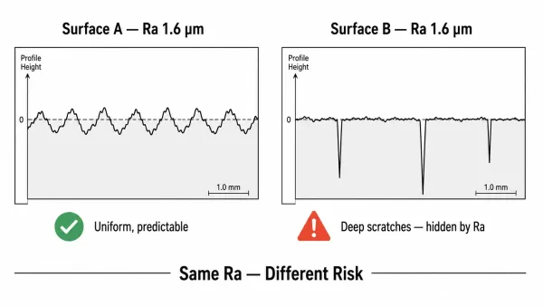
Two surfaces with the same Ra value (1.6 µm) can have very different profile shapes. Surface A has uniform waves; Surface B has deep scratches that Ra alone would not reveal.
Consider two surfaces, both with Ra 1.6 µm:
- Surface A has uniform, gentle waves — consistent and predictable.
- Surface B has a mostly smooth profile interrupted by a few deep scratches.
Both surfaces produce the same Ra reading. But Surface B may fail a sealing test because the deep scratches create leak paths, or it may cause premature coating failure after sheet metal surface finishing because the scratches can exceed the coating thickness.
This is why engineers working with sealing surfaces, fatigue-critical parts, or coated components often specify Ra and Rz together. Ra controls the average finish level; Rz catches the outliers that Ra hides. In some applications, Rsk (skewness) adds further insight by revealing whether the surface is peak-dominated or valley-dominated — a distinction that affects lubrication retention, paint adhesion, and contact mechanics.
When in doubt, specify Ra as your primary control and add Rz as a secondary requirement for critical surfaces. This combination captures both the average and the worst case without overcomplicating the callout.
FAQs
Need help specifying the right surface finish for your sheet metal parts? Our engineering team can review your drawings and recommend finish requirements that balance performance, manufacturability, and cost. [Request a DFM review →]