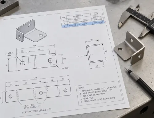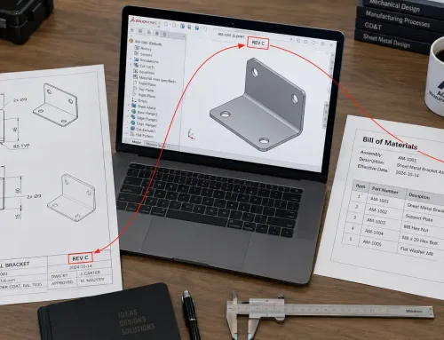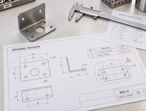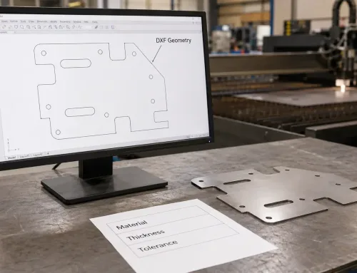

Most explanations of design intent start in a CAD system: define relations so that changing one dimension updates the model. That definition is useful for parametric modeling, but it is incomplete for manufacturing. Design intent is the purpose a part must serve—its function, fit, interfaces, and constraints—not only the numbers that describe its geometry.
When a fabricator understands that intent, DFM advice changes. The shop can tell you which tolerances matter, which features can be simplified, and which process choices preserve performance. Without intent, the only safe response is to follow the drawing exactly.
A Definition That Survives the Shop Floor
In engineering, design intent is the reasoning behind a design: what the part must do, under what conditions, and which relationships must hold for it to work.
CAD software often uses the same phrase for something narrower—how a model behaves when dimensions change. Sketch relations, feature order, and equation-driven dimensions capture modeling intent. That layer matters for design reuse and revisions, but it does not tell a sheet metal supplier which face is cosmetic, which hole must align to an assembly, or which wall must carry load.
For manufacturing, design intent is the functional brief behind the geometry. Dimensions and tolerances express that brief in measurable form. They are not the brief itself.
Design Intent Is Not Another Set of Dimensions
Drawings already carry many constraints. It helps to keep them in separate layers:
| Layer | What it states | What it does not state |
|---|---|---|
| Design intent | Why the part exists and what success looks like | Exact allowable variation |
| Nominal dimensions | Target geometry | Why that geometry was chosen |
| Tolerances | Permitted deviation from nominals | Which deviations break function |
| Specifications | Material, finish, inspection, and acceptance rules | The assembly purpose behind those rules |
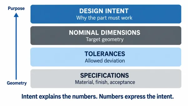
A stacked technical diagram of four information layers—Design Intent, Nominal Dimensions, Tolerances, and Specifications—with one short label describing what each layer states.
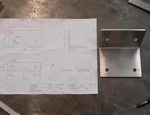
Consider a mounting hole on a sheet metal bracket. A drawing may call for Ø5.5 mm ±0.1 mm. The design intent might be: this hole locates the bracket on a chassis with a 5 mm fastener and must not shift under vibration. If the fabricator knows that, a supplier can flag when a proposed process change would affect hole position stability—or when a slightly different tolerance stack still preserves alignment.
Without the intent layer, every number looks equally critical. With it, both sides can distinguish functional requirements from drawing convention.
What Engineers Actually Intend a Part to Do
On fabricated parts, design intent usually shows up in three places.
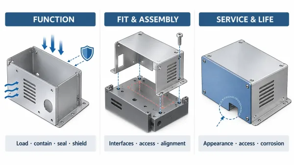
Three simplified panels show how design intent appears on fabricated parts: load or enclosure function, assembly fit at interfaces, and handling/service requirements.
Functional performance. The part must contain, support, shield, seal, or transfer load. Enclosure stiffness, EMI shielding, load paths in a bent bracket, and heat dissipation through a panel all belong here.
Fit and assembly. Interfaces with neighboring parts matter as much as absolute size: mounting patterns, keep-out zones, fastener access, cable routes, and datum schemes. A feature can be dimensionally correct and still fail if it blocks assembly.
Service and life. How the part is handled, cleaned, inspected, and replaced over time. Cosmetic faces, corrosion exposure, edge conditions for user contact, and access for maintenance all shape the design—even when they never appear as a single tolerance value.
Each of these is a reason behind the geometry. Engineers usually hold that reason in the model, the system architecture, or tribal knowledge. Buyers and fabricators only see what makes it onto the RFQ package.
How a Fabricator Reads Intent Before It Quotes
Before a quote is locked, an experienced fabricator looks for signals of intent in the drawing package:
- Which faces are marked cosmetic, and which are bare structure?
- Which dimensions are tied to assembly interfaces versus general form?
- Where are GD&T frames applied—and which features carry them?
- Are there notes about seal, ground, torque, or accessibility?
These questions separate functional critical features from formatting habits (for example, a default block tolerance copied from a template).
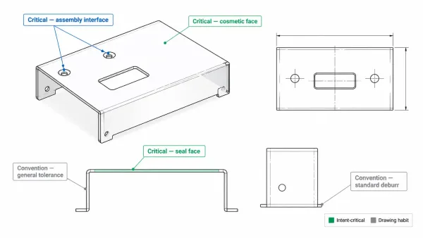
A simplified fabrication drawing highlights which callouts carry design intent (interfaces, seals, cosmetic faces) and which are general drawing conventions.
If intent is unclear, the shop quotes conservatively: tighter process control, more inspection, higher risk premiums, and fewer alternative proposals. If intent is clear, the same shop can offer options—another joint type, a different blank thickness, a simplified bend—without guessing which requirements are inviolable.
That is not salesmanship. It is how DFM review becomes useful instead of ornamental.
Why Clear Design Intent Improves DFM Advice
DFM (design for manufacturability) advice is only as good as the constraint set it works against. Design intent supplies that set.
Relaxing a tolerance is safe only when you know what the tolerance protects. A ±0.1 mm callout on a non-functional clearance may be widened if the required clearance is still met. Changing the same callout on a press-fit or sealing interface requires engineering review. Intent tells the fabricator which case applies.
Process and structure changes require a purpose check. Switching from welded corners to folded corners, from PEM inserts to tapped holes, or from machined detail to a standard bend can reduce cost and lead time. None of those changes are automatically acceptable. They are acceptable when they preserve load path, sealing, appearance, and assembly method—the stated intent.
Difficulty is often optional. Tight inside radii, deep boxes with narrow flanges, and complex cutouts increase scrap and fixturing cost. When the fabricator knows which features are functional, it can flag difficulty that exists only for geometric habit.
In short: manufacturers do not need more numbers. They need to know which numbers are load-bearing for the product—and which are incidental.
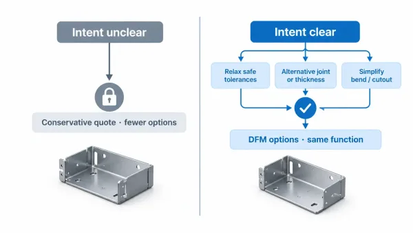
Two path diagram: unclear intent leads to a conservative locked quote; clear intent unlocks DFM options such as tolerance relief, alternative joints, and simplified bends.
How to Capture Design Intent Without Over-Specifying
Intent does not require a separate philosophy document. It needs a few disciplined habits at RFQ and drawing release.
- Attach purpose to critical features. A one-line note (“Hole locates bracket to chassis; maintain pattern position for assembly”) is more useful than another general tolerance block.
- Mark functional vs. cosmetic surfaces. Define appearance zones where color, scratch, or grain direction matters, and leave structure faces free of unnecessary cosmetic rules.
- State assembly assumptions. Fastener size and access, mating part class, seal or grounding needs, and allowed alternative processes give the fabricator room to propose real options.
- Invite DFM review before price is frozen. The cheapest time to adjust intent vs. geometry is at quote, not after the first batch is built wrong.
A compact RFQ that says what success looks like will get sharper feedback than a long drawing set that only says what the numbers are.
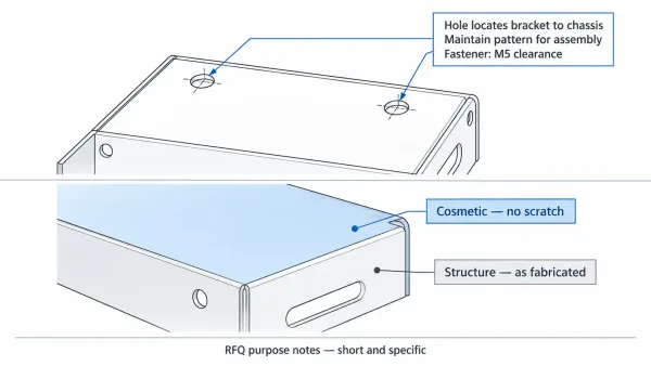
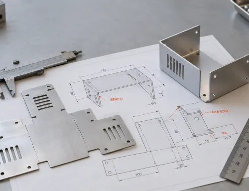
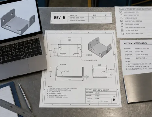
A small drawing fragment with two example callouts: a purpose note on a mounting hole and a surface note splitting cosmetic and structural faces.
Key Takeaways
- Design intent is the functional, assembly, and interface purpose of a part—not merely CAD model behavior and not another dimension list.
- CAD “design intent” (parametric relations) helps designers edit models; manufacturing design intent helps suppliers build and improve parts.
- Layers differ: intent (why) → nominals (target) → tolerances (allowable variation) → specs (how to verify).
- Fabricators use intent to separate critical features from drawing convention at RFQ and DFM review.
- Clear intent enables safe tolerance relaxation, alternative joints, and cost reduction that still meets product goals.
- Capture intent with short purpose notes, surface classification, assembly assumptions, and an early DFM review—not with keyword-heavy over-specification.